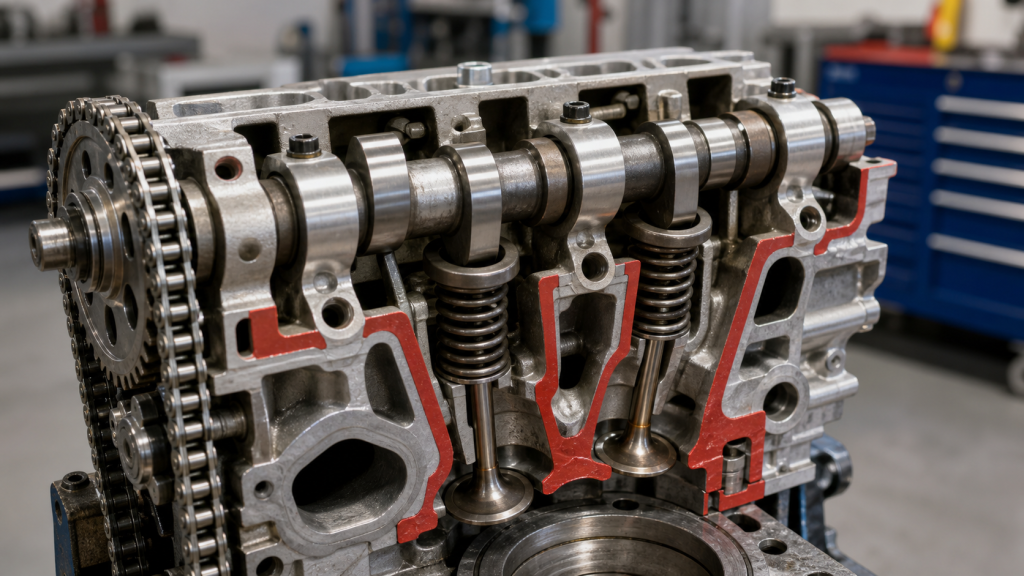
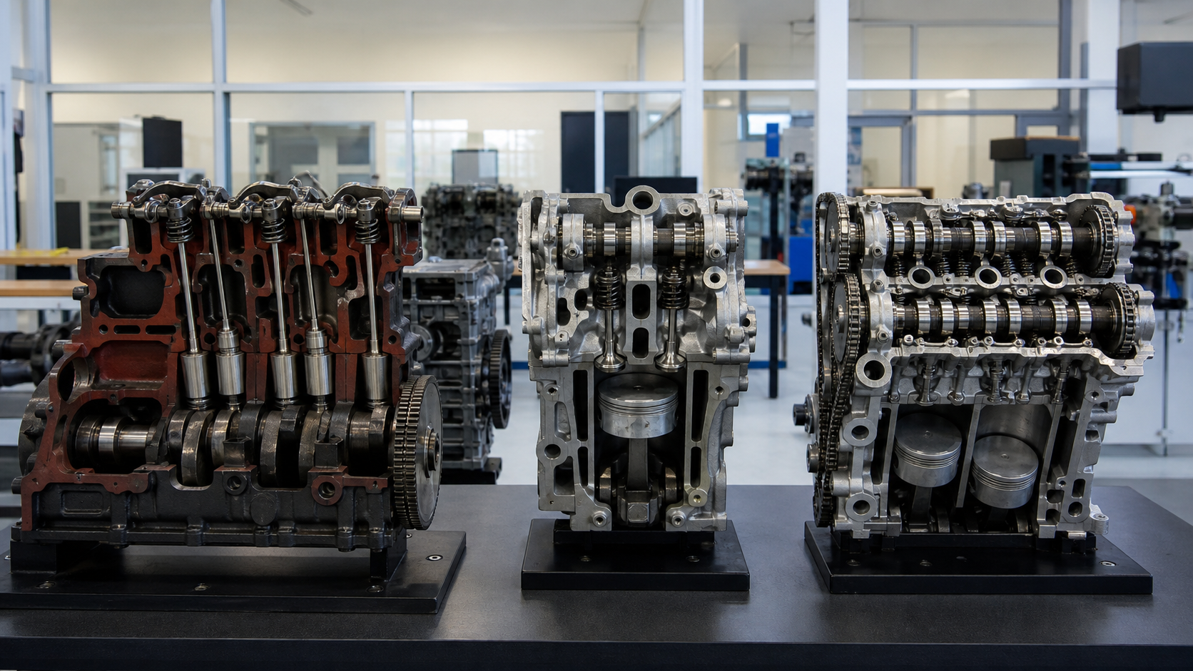
Camshaft classifications describe three different characteristics: where the shaft mounts in the engine, how force transfers from lobe to valve, and whether timing adjusts during operation. Single overhead cam (SOHC) and dual overhead cam (DOHC) refer to location and count, not material or manufacturing precision. Understanding the complete force path—from rotating lobe through intermediate components to the opening valve—reveals why these architectures perform differently and require different service approaches.
Key Takeaways
- Camshaft type can refer to location (cam-in-block, SOHC, DOHC), actuation method (direct-acting, finger follower, rocker arm), or timing control (fixed, variable phase, variable lift).
- The number of components between cam lobe and valve stem determines reciprocating mass, friction characteristics, and service access requirements.
- Cam-in-block layouts transfer force through lifters, pushrods, and rocker arms; SOHC and DOHC place camshafts in the head, shortening or eliminating the pushrod path.
- Direct-acting systems remove rocker-arm mass; rocker-operated systems provide adjustment flexibility and accommodate packaging constraints.
- Variable valve timing adjusts camshaft phase; variable lift changes the effective cam profile during operation.
- Service manuals define timing marks, lash procedures, and wear limits for each engine family.
Camshaft Type Can Mean Location, Construction, or Control
A camshaft converts crankshaft rotation into reciprocating motion that opens and closes valves. The shaft rotates at half crankshaft speed, driven by belt, chain, or gears. When mechanics, parts catalogs, or service documentation refer to camshaft types, the classification system depends on context.
Location classification divides engines into cam-in-block (overhead valve/OHV), single overhead cam (SOHC), and dual overhead cam (DOHC). The camshaft mounts either in the engine block below the head or directly in the head casting. This determines valvetrain height, component count, and service access.
Actuation classification describes the mechanical path from lobe to valve: direct-acting followers that sit on valve stems, finger followers or rocker arms that pivot between lobe and valve, or pushrods connecting block-mounted cams to head-mounted rockers. Component count and mass in this path affect friction and maximum reliable operating speed.
Timing-control classification separates fixed-profile camshafts from variable valve timing (VVT) systems that adjust phase angle, and variable valve lift (VVL) systems that alter effective lobe geometry during operation.
The same engine uses multiple classification terms simultaneously. A turbocharged inline-four might be DOHC (two camshafts per head), direct-acting (bucket followers), and dual-VVT (phasers on both camshafts).
Cam-in-Block and Pushrod Layouts
In cam-in-block layouts, the camshaft mounts in the engine block between crankshaft and cylinder head. Each lobe contacts a lifter riding in a block bore. Force transfers through a pushrod—a steel or aluminum tube—to a rocker arm pivoting in the cylinder head. The rocker pushes the valve stem downward against spring pressure.
The complete force path: cam lobe → lifter → pushrod → rocker arm → valve stem. Each interface adds clearance, mass, and friction. This extended path limits practical valve-spring loads compared to overhead-cam designs.
Hydraulic lifters use oil pressure to maintain zero clearance between pushrod and rocker, eliminating manual lash adjustment. They add compliance to the valvetrain and require stable oil pressure throughout the operating range.
The architecture offers specific advantages. Cylinder heads contain only valves, springs, rocker gear, and cooling passages, reducing head height and weight. The camshaft sits close to the crankshaft, shortening timing-chain length and reducing stretch risk. Cam and lifter service requires timing-cover removal and crankshaft positioning but not head removal.
V8 truck engines, large-displacement applications, and some industrial engines use cam-in-block layouts where packaging height matters more than high-rpm breathing. A V8 with valley-mounted camshaft operates sixteen valves through sixteen pushrods total, avoiding the cost of four overhead camshafts and dual timing chains.
Single Overhead Camshaft Systems
Single overhead camshaft (SOHC) layouts mount one camshaft in each cylinder head, directly above the valves. The shaft rides in bearing journals machined into the head or separate bearing caps. Timing belt or chain connects the cam sprocket to the crankshaft sprocket at 2:1 reduction.
In four-valve-per-cylinder SOHC engines, one camshaft operates both intake and exhaust valves. Intake and exhaust lobes alternate along the shaft length. The force path shortens compared to pushrod layouts: cam lobe → rocker arm or finger follower → valve stem. Eliminating the pushrod reduces reciprocating mass.
The actuation method varies with valve spacing and packaging requirements. Some SOHC engines use rocker arms for all valves; others use finger followers; some combine both methods in the same head. Valve-lash adjustment uses either hydraulic lash adjusters built into rockers or followers, or manual shim or screw-and-locknut systems requiring periodic inspection.
The cam-drive system becomes more complex than cam-in-block layouts because greater distance from crankshaft to camshaft requires longer chains or belts, sometimes with intermediate sprockets or guides. Service manuals specify timing marks, drive-component replacement intervals, and lash procedures for each engine family.
Worn timing components allow the camshaft to drift from correct crankshaft relationship, changing valve events. In interference engines, sufficient timing drift causes pistons to contact open valves during rotation.
Camshaft replacement requires removing timing cover, belt or chain, and bearing caps in the documented loosening sequence. Some engines allow camshaft service with the head installed; others require head removal for spring-compressor access.
Dual Overhead Camshaft Systems
Dual overhead camshaft (DOHC) layouts place two camshafts in each cylinder head: one operates intake valves, the other exhaust valves. This separation permits independent timing control, larger valve diameters, and straighter ports. The force path shortens further when direct-acting followers eliminate rockers: cam lobe → bucket follower → valve stem.
In four-valve-per-cylinder DOHC engines, each camshaft operates two valves per cylinder. Both shafts rotate in the same direction, driven by a single timing belt or chain connecting both cam sprockets to the crankshaft sprocket. Some designs use a primary chain to one camshaft and secondary chain or gears between camshafts.
Direct-acting bucket followers sit directly on valve stems, riding under the cam lobe. A hardened shim between bucket and cam or between bucket and valve stem provides the wear surface. The follower reciprocates in a head bore, guided by bore walls rather than pivot points. This arrangement minimizes side loads on valve stems.
Manufacturing and service complexity increases compared to SOHC or cam-in-block designs. Each head requires two camshaft bores, two bearing-cap sets, two camshaft seals, and double the lobe count. The timing system must maintain phase accuracy for two camshafts per head. Belt or chain replacement requires locking tools to hold all camshafts at specified alignment marks simultaneously.
Valve-lash adjustment in direct-acting DOHC engines uses shim-over-bucket or shim-under-bucket systems. The technician measures clearance between lobe base circle and bucket or shim, calculates required shim thickness, removes the old shim, and installs the correct replacement. This adjustment method typically occurs during major service intervals or when valve-recession symptoms appear, not on a routine maintenance schedule.
Direct Acting, Finger Follower, and Rocker Operation
The actuation method determines the mechanical connection between lobe and valve stem, affecting mass distribution, adjustment access, and packaging geometry.
Direct-acting systems place a bucket follower on the valve stem with the cam lobe riding on the follower’s top surface. The follower moves in a bore machined into the head. A hardened shim sits between cam and follower or between follower and valve stem depending on design. This minimizes reciprocating mass and side loads. Valve-lash adjustment requires measuring clearance and selecting shims from an available range.
Finger followers are short levers pivoting on hydraulic lash adjusters or fixed shafts. The cam lobe contacts one end, the opposite end contacts the valve stem. Pivot location relative to contact points creates the valve-lift ratio. Finger followers reduce mass compared to full-length rocker arms while accommodating valve-to-cam spacing constraints. Hydraulic lash adjusters in the pivot automatically maintain zero clearance using engine oil pressure.
Rocker-arm systems use longer levers pivoting on shafts or studs mounted in the head. The cam lobe or pushrod contacts one end, the opposite end contacts the valve stem. Pivot location determines rocker ratio—the relationship between cam lift and valve lift. A ratio greater than 1:1 multiplies lobe lift at the valve stem, allowing smaller cam lobes. Rocker systems appear in SOHC engines and all cam-in-block engines. Lash adjustment uses screw-and-locknut adjusters, hydraulic adjusters in the pivot, or hydraulic lifters at the pushrod interface.
Service manuals specify valve-lash clearances, measurement procedures, and adjustment methods. Cold specifications differ from hot specifications due to thermal expansion. Insufficient clearance prevents valves from fully closing, causing compression loss and valve-face burning. Excessive clearance creates impact loads, accelerating wear on lobes, followers, and valve-stem tips.
Fixed Timing, Variable Timing, and Variable Lift
The timing-control system determines whether valve events remain constant or adjust during operation.
Fixed-timing camshafts have machined lobe profiles that define valve opening and closing points relative to crankshaft position. These events remain constant regardless of engine speed or load. The camshaft installs with timing marks aligned to crankshaft position, maintained by belt, chain, or gear drive. Fixed-timing systems are mechanically simple and require no electronic control. Timing optimized for low-speed torque compromises high-speed breathing, and vice versa.
Variable valve timing (VVT) systems adjust camshaft phase relative to the crankshaft, advancing or retarding valve events. A cam phaser—an oil-pressure-actuated device on the cam sprocket—rotates the camshaft within a limited range. The engine control module commands a phaser solenoid valve to direct oil pressure to advance or retard chambers. Advancing the intake camshaft opens intake valves earlier, affecting low-speed torque and part-throttle economy. Retarding the exhaust camshaft holds exhaust valves open longer, increasing internal exhaust-gas recirculation. DOHC engines with independent intake and exhaust cam phasers offer wider tuning range.
Variable valve lift (VVL) systems change cam-lobe profile or follower geometry during operation. Some implementations use multiple lobes per valve—a low-lift profile for normal operation and a high-lift profile for high output—with a hydraulic pin locking rocker arms together at preset conditions to engage the high-lift lobe. Other systems use electrically adjusted eccentric shafts that change the pivot point of intermediate levers, continuously varying valve lift. Variable lift systems improve part-load efficiency by reducing throttling losses.
Diagnosing VVT and VVL systems requires scan-tool access to commanded and actual camshaft positions, phaser solenoid operation, and oil-pressure supply verification. Mechanical timing verification using a dial indicator or timing light remains necessary to confirm phaser home position before setting base timing. Service manuals provide phaser relearn procedures and oil-specification requirements because phasers depend on precise viscosity and pressure characteristics.
SOHC vs DOHC Decision Table
|
Factor |
Cam-in-Block (OHV) |
SOHC |
DOHC |
|---|---|---|---|
|
Camshafts per head |
0 (block-mounted) |
1 |
2 |
|
Typical valve count per cylinder |
2 |
2-4 |
4-5 |
|
Valvetrain force path |
Cam → lifter → pushrod → rocker → valve |
Cam → rocker or follower → valve |
Cam → follower → valve (or cam → rocker → valve) |
|
Cylinder head height |
Low (valves only) |
Medium |
Tall (two cams plus valve gear) |
|
Timing-system length |
Short (cam near crank) |
Medium |
Long (cams far from crank) |
|
Valve-lash adjustment |
Hydraulic or manual rocker adjustment |
Hydraulic or shim/screw adjustment |
Shim-under-bucket or hydraulic |
|
Variable timing implementation |
Limited (single cam, long valvetrain) |
One phaser per head possible |
Independent intake/exhaust phasers possible |
|
Common applications |
V8 trucks, large-displacement engines |
Economy cars, mid-range sedans |
Performance engines, turbocharged applications |
Engine family, intended use, and manufacturing constraints determine valvetrain architecture. Cam-in-block engines dominate applications where low engine height, simple valve gear, and low-rpm torque outweigh high-rpm capability. SOHC engines balance cost and performance in mainstream applications. DOHC engines appear where maximum breathing efficiency and variable-timing capability justify added complexity.
When sourcing replacement camshafts, part numbers must match engine family, model year, and emissions calibration. Camshafts are not interchangeable between engine variants even when displacement matches. Lobe profiles, bearing journal diameters, sprocket mounting dimensions, and phaser interfaces differ. Rebuilders and machine shops need the vehicle identification number, engine code, and build date to verify fitment and timing specifications.
FAQs
Can I upgrade from SOHC to DOHC in an existing engine?
No. The cylinder head casting, camshaft bores, valve angles, port shapes, timing-cover mounting, and timing-drive layout differ structurally between SOHC and DOHC designs. Converting requires replacing the entire cylinder head assembly, timing system, engine control module calibration, and often the engine block if bearing and oil-passage locations are incompatible. The engineering and parts cost exceeds complete engine replacement with the desired configuration.
What causes cam-lobe wear and how is it detected?
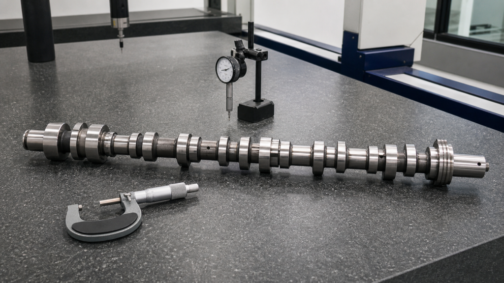
Cam-lobe wear results from inadequate lubrication, incorrect oil viscosity, contaminated oil, excessive valve-spring loads, or follower misalignment. Wear appears as flattened or scuffed areas on lobe peaks, reducing valve lift and causing rough idle, misfires, and power loss. Detection requires removing the camshaft or valve cover and inspecting lobe profiles with a micrometer or dial indicator. Service manuals specify minimum lobe-height dimensions and maximum variation between cylinders. Cam-lobe wear often damages the mating follower or rocker-arm surface, requiring both parts to be replaced together.
Do all DOHC engines use direct-acting followers?
No. Many DOHC engines use finger followers or rocker arms to accommodate packaging constraints, reduce valve-stem side loads, or provide lash adjustment using hydraulic adjusters instead of shims. Direct-acting bucket followers minimize valvetrain mass and friction but require the camshaft positioned directly over valve stems, which limits valve-angle flexibility and increases cylinder-head height. The actuation method depends on the designer’s priorities for performance, cost, service intervals, and packaging.
How often should valve lash be checked?
The service interval depends on the adjustment method and engine design. Engines with hydraulic lash adjusters require no routine valve-lash service—inspection occurs when symptoms appear or during major service. Engines with manual screw-and-locknut adjusters require periodic inspection; the service manual for the specific engine family specifies the interval. Direct-acting engines with shim adjustment may specify inspection only when valve noise or compression loss develops. Consult the factory service manual for inspection intervals, clearance specifications, and adjustment procedures.
Are aftermarket performance camshafts interchangeable with stock camshafts?
Physical interchangeability requires matching bearing journal diameters, overall length, sprocket mounting, and oil-passage alignment. Functional compatibility requires verifying that new lobe profiles do not cause piston-to-valve interference, that valve springs can handle increased lift and duration, that fuel and ignition systems can be recalibrated for new valve events, and that emissions compliance is maintained if required. Installing a performance camshaft without verifying piston-to-valve clearance at maximum lift and overlap can cause catastrophic damage. A machine shop should measure piston-to-valve clearance with heads installed and the engine rotated through two full crankshaft revolutions before starting.
Conclusion
Camshaft classification separates into location (cam-in-block, SOHC, DOHC), actuation method (direct-acting, finger follower, rocker arm), and timing control (fixed, variable phase, variable lift). The force path from rotating lobe through intermediate components to opening valve determines reciprocating mass, friction characteristics, and service requirements. When ordering replacement camshafts or diagnosing valve-timing faults, obtain the service manual for the exact engine code and verify that part numbers, bearing dimensions, lobe profiles, and phaser interfaces match original specifications. Measure valve lash and piston-to-valve clearance before starting a rebuilt engine, and follow timing-mark alignment and torque specifications exactly as written in the factory procedure.