
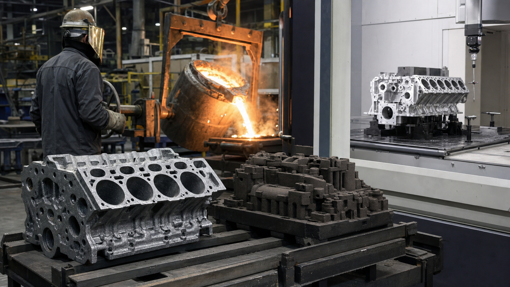
Before the first drop of metal enters the mold, the internal passages that carry coolant around cylinders and route pressurized oil to bearing surfaces already exist—as sand. Engine blocks are made through sand casting followed by precision machining. The manufacturing process begins with pattern equipment that shapes reusable sand cores for water jackets and oil galleries, continues through metal pouring and heat treatment, and concludes with CNC machining that establishes the datum surfaces controlling bore spacing, deck flatness, and crankshaft centerline location. Each step must preserve dimensional accuracy while forming a structure strong enough to contain combustion pressure and rigid enough to maintain bearing alignment under load.
Key Takeaways
- Sand cores form internal cooling and lubrication passages before molten iron or aluminum enters the mold cavity
- Casting produces the block’s basic shape and internal geometry; machining creates the precision datums that determine engine assembly accuracy
- Heat treatment stabilizes the casting and relieves residual stress before major material removal begins
- Bore honing and deck surfacing must meet specified diameter, surface finish, and perpendicularity for proper ring seal and head gasket performance
- Final inspection includes dimensional verification, porosity checks, and pressure or vacuum leak testing to confirm passage integrity
Design for Casting, Machining, Cooling, and Load
Engineers design engine blocks to satisfy conflicting requirements. The casting must allow sand cores to be inserted and removed, so internal passages cannot include reverse angles or undercuts that would trap the core. Wall sections around cylinders must be thick enough to conduct combustion heat to the water jacket but thin enough to minimize thermal expansion differences between the bore and the rest of the structure. Crankshaft main bearing saddles must provide a continuous load path to the cylinder area while leaving room for oil drain-back passages and structural ribs.
The designer locates machined datums—typically the crankshaft centerline and deck surface—to minimize cumulative tolerance stack when cam timing, valve seat position, and piston-to-head clearance are calculated. On inline engines, the main bearing saddles share a single horizontal plane, making it possible to bore all main journals in one setup. V-configuration blocks require separate datum surfaces for each cylinder bank, and the included angle between banks must be held during both casting solidification and subsequent machining operations.
Material choice follows the engine’s operating conditions. Cast iron blocks offer superior wear resistance for the cylinder bores and better damping of combustion vibration, while aluminum blocks reduce weight substantially for the same displacement. Aluminum requires either cast-in iron liners or thermal-spray bore coatings, adding process steps but enabling direct coolant contact with the liner outer surface for improved heat transfer.
Patterns, Core Boxes, and Internal Passage Formation
The pattern is a full-size replica of the finished casting’s exterior, machined from wood, plastic, or aluminum and mounted in a two-part flask that separates along the block’s longest dimension. When packed with bonded sand and separated, the pattern leaves a cavity matching the block’s outer contours and the spaces where cylinder walls, main bearing webs, and mounting bosses will solidify. The pattern includes extra material—the machining allowance—on surfaces that will later be cut to final size.
Core boxes produce the sand shapes that occupy the spaces meant to remain hollow. A water jacket core sits inside the mold cavity before pouring, and when the metal solidifies around it, the core’s exterior becomes the interior wall of the cooling passages. The core must be strong enough to resist the pressure and buoyancy of molten metal but weak enough to break apart and shake out through the core-print openings after solidification. Modern core sand uses resin binders that cure with heat or catalytic gas, creating cores rigid enough to be handled individually yet brittle enough to fragment during shakeout.
Oil gallery cores run horizontally through the block deck and vertically through main bearing webs, intersecting at drilled crossover passages added during machining. A separate core forms each cylinder bore’s water jacket, and registration features on the core boxes ensure that coolant passage walls maintain minimum thickness around the entire bore circumference. The assembly sequence matters: main gallery cores install first, followed by cylinder jacket cores, and finally the pattern halves close around the complete core package. Any misalignment at this stage will produce a casting with offset passages or thin walls that may fail during service.
Melting, Pouring, Solidification, and Shakeout
Melting takes place in an induction furnace for cast iron or a reverberatory furnace for aluminum alloys. Iron blocks typically use gray cast iron with carbon and silicon content that produces graphite flakes, improving machinability and providing natural lubrication in cylinder bores. Aluminum blocks use silicon-containing alloys for fluidity and low thermal expansion, often with copper additions for strength at elevated temperatures.
The metal temperature at pouring must be high enough to fill thin sections and flow around cores without premature solidification, but not so high that core binders break down prematurely or excessive gas is absorbed. Pouring rate follows a calculated curve: too slow and the stream freezes before the mold fills, too fast and turbulence entrains air or erodes the sand surface. The mold fills from bottom to top through a gating system designed to minimize turbulence, and a riser at the highest point supplies additional metal as the casting shrinks during cooling.
Solidification begins at the mold walls and progresses inward. Directional solidification is controlled by varying wall thickness and adding external chills—metal blocks that extract heat faster than sand—to ensure that the last metal to freeze is in the riser, not trapped in the middle of a heavy section where shrinkage would create internal porosity. For cast iron, cooling rate determines the microstructure and hardness; sections that cool too quickly become hard and difficult to machine, while sections that cool slowly may have coarse graphite and reduced strength.
After the casting cools below the sand’s breakdown temperature, mechanical vibration or tumbling breaks apart the cores. Water jacket and oil gallery cores exit through their print openings, leaving the hollow passages that will later carry coolant and lubricant. A visual inspection at this stage identifies surface defects, sand inclusions, or misrun areas where the metal failed to fill completely. Castings with visible cracks, excessive porosity, or broken-through water jackets are scrapped immediately rather than consuming machining capacity.
Heat Treatment, Cleaning, and Casting Inspection
Cast iron blocks undergo stress relief at controlled temperatures, then slow-cool to room temperature. This thermal cycle reduces residual stresses from uneven cooling rates during solidification and minimizes dimensional movement during subsequent machining. Aluminum blocks may receive solution treatment, quenching, and artificial aging depending on alloy composition, strengthening the material through controlled precipitation of fine intermetallic particles.
Shot blasting removes sand residue, core material, and oxide scale from all surfaces. Steel shot or grit propelled by compressed air or centrifugal wheels impacts the casting at high velocity, fracturing adhered sand and leaving a uniformly textured surface. The process also peens the surface, introducing compressive stress that improves fatigue resistance in areas subject to cyclic loading. Water jacket and oil gallery passages require separate flushing with high-pressure water to dislodge loose core sand before machining begins.
Dimensional inspection at this stage verifies that the as-cast block falls within the tolerance envelope expected after pattern wear and normal process variation. Inspectors measure critical distances—deck height, main bearing saddle spacing, cylinder centerline locations—using coordinate measuring machines or dedicated fixtures with dial indicators. Castings outside the acceptable range are either scrapped or sorted into groups requiring different machining programs with adjusted tool offsets.
Radiographic or ultrasonic inspection detects internal defects invisible from the surface. Porosity near cylinder bores or main bearing webs can initiate cracks under load, and voids in water jacket walls may open pathways for coolant to reach the crankcase. Foundries that supply engines for critical applications—marine, industrial, or performance automotive—typically X-ray every block or use statistical sampling plans when volume and consequence levels permit accepting a calculated defect rate.
Datum Creation and Major Machining Operations
The first machining operation establishes the primary datum: either the crankshaft centerline or the deck surface, depending on the engine family’s design hierarchy. Transfer machines or CNC machining centers position the casting using sacrificial pads or rough surfaces, then rough-bore the main bearing saddles or face-mill the deck to create a reference plane for all subsequent operations. Once this datum exists, the casting can be located repeatably, and the remaining features—cylinder bores, camshaft bores, lifter bores, accessory mounting holes—are machined in relation to it.
Main bearing saddle machining follows a precise sequence. The casting sits on v-blocks that locate the outer diameter of the rough saddles, and a line-boring tool with multiple cutting heads machines all saddles in a single pass, guaranteeing that their centerlines are colinear and parallel to the datum surface. Bearing cap faces and cap bolt holes are machined with the caps torqued in place, ensuring that bore distortion from cap-fastening loads is built into the as-machined geometry. Some designs use fracture-split caps: a single rough bore is machined, then the cap is cracked apart along a carefully controlled fracture path, creating mating surfaces with microscopic interlocking features that locate the cap more accurately than a traditional parting line.
Cylinder bore machining begins with rough boring to within a small margin of final size, leaving material for the honing operation that creates the final diameter and surface finish. Coolant passages drilled from the deck surface intersect the cast water jacket, and oil gallery holes connect the cast main gallery to cam bearings, lifter bores, and deck-surface oil feed holes. Each drilled hole creates an intersection with a cast passage, and inspection after drilling verifies that the hole broke through into the intended gallery rather than missing it due to core misalignment or walking during the drilling operation.
Honing, Deck Finishing, Deburring, and Washing
Cylinder honing removes the rough-boring tool marks and produces a surface with a controlled crosshatch pattern—intersecting spiral scratches at a specified angle. The hone head carries multiple abrasive stones that expand radially against the bore wall, and the tool reciprocates while rotating to create the crosshatch geometry. The final stone grit determines surface finish: coarser finishes retain more oil for initial break-in, while finer finishes reduce oil consumption after the rings have seated. Surface finish is measured and must fall within the range specified by the piston ring manufacturer for their ring face profiles and coatings.
The crosshatch angle affects oil control. Too steep and oil drains away too quickly, increasing friction and wear. Too shallow and oil film thickness becomes excessive, allowing blow-by and oil consumption. The honing stone’s rotational and reciprocating speeds are adjusted to produce the specified angle, and inline process measurement systems verify that each bore meets specification before the block advances to the next station.
Deck surface grinding or milling creates the flatness and finish required for head gasket sealing. Flatness specifications vary by gasket type—multi-layer steel gaskets typically require tighter control than composite gaskets—and are measured with a precision straightedge and feeler gauges or with a coordinate measuring machine. Surface finish must be smooth enough to seal against the gasket but rough enough to prevent micro-welding between the block and gasket surfaces.
All machined holes and intersecting passages accumulate burrs and chips during cutting operations. High-pressure washing combined with manual deburring removes these contaminants, which would otherwise circulate through the oiling system and damage bearings or oil-control components. Thermal deburring—momentary combustion of methane-oxygen mixture inside the block—burns away burrs in passages too small or complex for mechanical access, and the resulting flash and soot are removed by subsequent washing.
Dimensional, Porosity, and Leak Verification
Final inspection measures the block’s critical dimensions and confirms that internal passages are intact and leak-free. Coordinate measuring machines probe cylinder bore diameters at multiple depths and orientations, recording taper and out-of-round conditions that would prevent proper ring sealing. Main bearing saddle diameters, deck flatness, and cylinder centerline spacing are compared to drawing tolerances, and any block outside specification is either scrapped or routed to a rework operation if the deviation can be corrected by additional machining.
Leak testing verifies water jacket and oil gallery integrity. Pressure testing involves plugging all openings with threaded or expanding plugs, filling the passages with air or water at specified pressure, and monitoring for pressure decay over a fixed time interval. Any drop indicates a leak through a crack, porosity, or improperly sealed core plug. Vacuum testing applies negative pressure and detects leaks by observing vacuum decay or by applying a tracer gas and sniffing for leaks at suspected locations. Some foundries use both methods sequentially: vacuum testing for gross leaks followed by pressure testing for verification.
Porosity that does not penetrate completely through a wall may still be rejected if it reduces load-bearing capacity or creates a path for future crack propagation. Ultrasonic inspection or dye-penetrant testing identifies subsurface voids and surface-breaking porosity that passed visual inspection. Blocks intended for high-specific-output engines—supercharged, turbocharged, or high-compression naturally aspirated—typically face stricter porosity acceptance criteria than blocks for lower-stress applications.
FAQs
Why do some engine blocks have cylinder liners while others don’t?
Cast iron blocks often run piston rings directly against the bore surface because gray cast iron’s graphite flakes provide natural lubrication and wear resistance. Aluminum blocks require either cast-in iron liners or thermal-spray coatings because aluminum is too soft to resist ring wear, and its higher thermal expansion makes maintaining proper running clearance difficult. Liners add cost and weight but allow local replacement of worn cylinders without replacing the entire block. The choice depends on the engine’s design priorities: weight reduction favors thermal-spray coatings, while repairability and durability favor pressed-in liners. Service manuals specify whether a particular engine uses parent-bore, pressed-liner, or slip-fit liner construction, and this determines whether oversized pistons or liner replacement is the correct repair for worn bores.
What causes porosity in engine block castings?
Porosity forms when dissolved gas comes out of solution during solidification or when shrinkage creates voids in sections that freeze last. Hydrogen absorbed from moisture in the mold or melting atmosphere is the primary cause in aluminum castings, while cast iron porosity more often results from improper riser placement allowing isolated pockets to solidify without a feed path for compensating metal. Turbulent pouring entrains air bubbles, and excessive pouring temperature increases gas solubility during filling, with the gas later forming pores as the metal cools. Porosity near bearing saddles or cylinder bores weakens the structure and may initiate cracks under cyclic loading, while porosity in water jacket walls can create leak paths. Foundries control porosity through degassing treatments, optimized gating design, directional solidification measures, and strict control of melting conditions. Radiographic inspection identifies internal porosity before machining investment is made, and surface porosity is revealed during machining or leak testing.
Can engine blocks be repaired after cracking?
Cracks in non-structural areas—cosmetic ribs, accessory mounting bosses, or isolated water jacket regions—can sometimes be repaired by welding or metal-stitching if the service manual permits it and the crack has not propagated into a load-bearing section. Cracks through cylinder bores, main bearing webs, or head bolt boss areas typically render the block unrepairable because proper welding requires preheating the entire casting to reduce thermal stress, followed by controlled cooling and stress-relief heat treatment that would distort machined datums beyond acceptable tolerance. The repair cost and dimensional verification required usually exceed replacement cost with a new or remanufactured block. Engine blocks subject to severe overheating, detonation, or hydro-lock impact often develop multiple cracks that may not be immediately visible, making thorough magnetic-particle or dye-penetrant inspection necessary before attempting any repair.
How do V-configuration blocks maintain the angle between cylinder banks?
The included angle between cylinder banks is controlled during casting by cores and pattern geometry, then maintained during machining by fixtures that reference both deck surfaces simultaneously. The angle affects crankshaft journal phasing, valve timing overlap between banks, and exhaust pulse interference. Any deviation changes the combustion interval timing and can create vibration or uneven firing. Machining centers locate the casting using both deck surfaces or a combination of deck and main saddle datums, and the cylinder bore machining program calculates each bore’s position from these references. Inspection measures the actual angle using precision angle blocks or trigonometric calculation from coordinate measurements, comparing the result to drawing tolerance. Heat treatment before machining is particularly important for V-blocks because unrelieved residual stress in the junction between banks can cause warping during subsequent material removal.
What tolerances are critical in engine block manufacturing?
Cylinder bore diameter must match the piston-to-bore clearance specification in the service manual for the specific engine model. Main bearing saddle bore diameter determines crankshaft bearing clearance, controlled by bearing shell thickness. Deck flatness affects head gasket sealing and must remain within limits specified by the gasket manufacturer. Bore-to-bore spacing and deck height control piston-to-head clearance at top dead center, critical for preventing contact during valve overlap when both intake and exhaust valves are off their seats. All tolerance values vary by engine model, and actual dimensions and acceptable ranges appear in the service manual or machining drawing, not as universal figures. Inspection records document that critical dimensions fall within specification before the block is released for assembly.
Conclusion
Engine blocks move through sand casting and precision machining in a sequence where each step depends on accurate completion of the previous operation. The casting creates internal passages and the basic structural form, heat treatment stabilizes dimensions and mechanical properties, and machining establishes the datum surfaces that control assembly geometry. Final inspection confirms that dimensions, surface finishes, and passage integrity meet specification before the block can receive bearings, pistons, and rotating assemblies. When evaluating replacement blocks or selecting a supplier for remanufacturing cores, request dimensional inspection reports showing bore diameter, deck flatness, and saddle bore measurements compared to the original equipment specification, along with documented leak-test results confirming water jacket and oil gallery integrity.