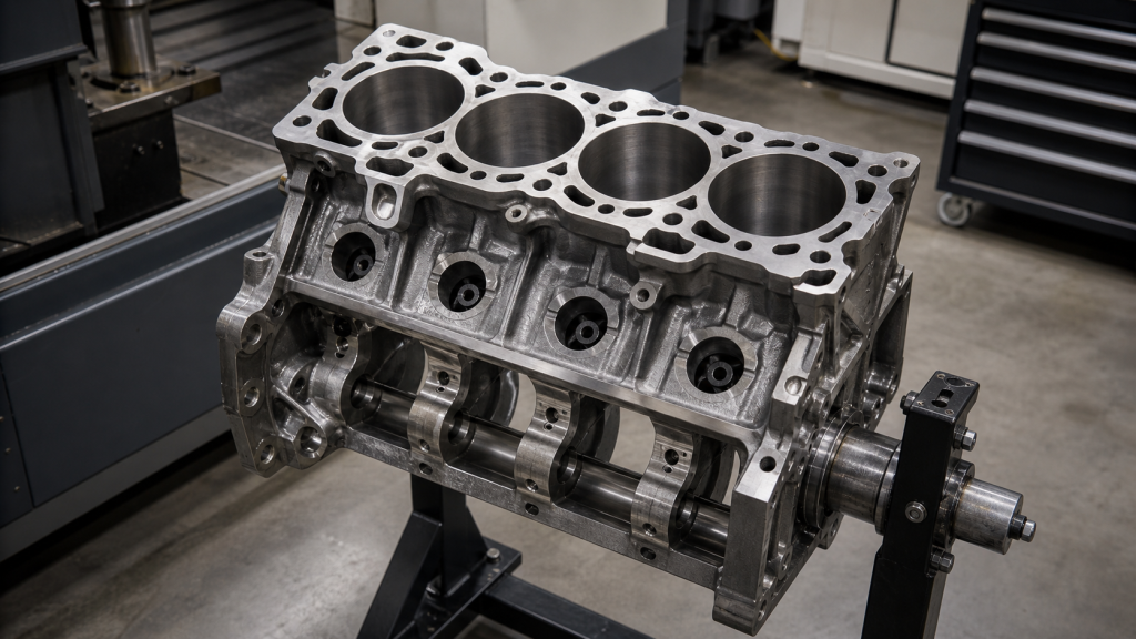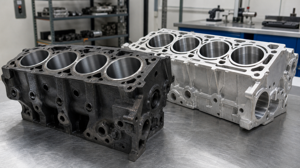
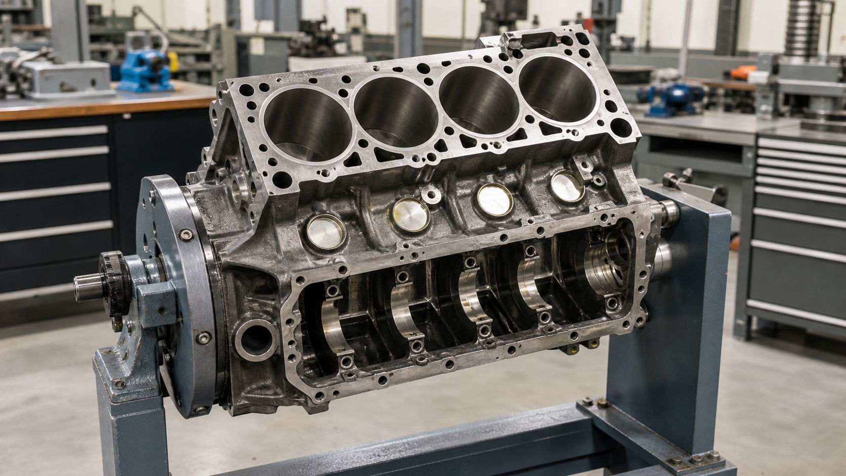
An engine block diagram shows permanent casting features and machined interfaces, not removable parts. The block is the main structural housing containing cylinder bores, main bearing saddles, and internal passages. Components installed into the block—pistons, crankshaft, camshaft, oil pump—appear in assembly drawings but are separate parts. Reading a block diagram requires identifying the casting architecture, machined datums, coolant jackets, oil galleries, and mounting surfaces that remain after all rotating assemblies and covers are removed.
This distinction matters during inspection, rebuilding, and sourcing. A diagram labels the block’s cylinder bores, deck surface, crankcase, main saddles, and core plug openings as integral casting features. The piston, rings, crankshaft, bearings, and head bolts are installed components. When you measure bore diameter, deck flatness, or main bearing bore alignment, you inspect the block itself. When you replace a crankshaft or install new bearings, you work with parts that fit into the block’s machined interfaces.
Key Takeaways
- Engine block diagrams show casting features, machined surfaces, and permanent passages—not the rotating assemblies or covers installed into them.
- Deck views identify cylinder bores, head bolt holes, coolant passages, and the fire-ring sealing area that mates with the head gasket.
- Crankcase and side views reveal main bearing saddles, oil galleries, core plug locations, bellhousing face, and accessory mounting pads.
- Front and rear views show timing cover interface, crankshaft seal bore, flywheel mounting surface, and rear main seal housing.
- Machined datums—deck surface, main bearing bores, camshaft bores—are the zero references for bore alignment, surface finish, and dimensional inspection.
- Service manuals provide bore diameter, deck flatness limits, main bearing bore alignment tolerance, and gallery plug torque values specific to each engine family.
How to Orient an Engine Block Diagram
Start by identifying the deck surface—the flat, machined top of the block where the cylinder head mounts. In a deck view, you see cylinder bores arranged in their firing order, coolant passages between bores, and head bolt or stud holes. Inline engines show bores in a single row. V-engines show two angled banks. Horizontally opposed engines show two banks at 180 degrees.
A side view reveals the crankcase opening, main bearing saddles, oil pan rail, and external mounting bosses. Count the main bearing saddles to confirm crankshaft journal count. Four-cylinder engines typically have five mains, while V8 engines commonly use five mains in automotive designs. Diesel and marine engines may use additional mains for rigidity.
Front views show the timing cover mounting face, front main bearing seal bore, and accessory drive mounting pads. Rear views show the bellhousing face, flywheel or flexplate mounting flange, and rear main seal housing. The crankcase view—looking up from the oil pan rail—displays the crankcase interior, oil gallery openings, windage tray mounting points, and the bottom side of main bearing caps or bedplate.
Diagrams use section cuts to expose internal oil galleries, coolant jackets, and core plug cavities. A longitudinal section runs front to back through the crankshaft centerline. A transverse section cuts through a cylinder bore to show liner thickness, coolant jacket width, and deck thickness. Cross-reference the diagram with the engine family service manual to confirm passage routing and plug locations.
Deck, Cylinder Bores, Liners, and Fire-Ring Area
The deck is the top machined surface of the block, perpendicular to the cylinder bore centerline. Deck height determines piston-to-head clearance and compression ratio. During resurfacing, material is removed to restore flatness. Service manuals specify maximum material removal and minimum deck height for each engine. Exceeding that limit affects piston-to-valve clearance or compression ratio.
Cylinder bores are the vertical holes where pistons travel. Bores may be machined directly into the block casting or fitted with pressed-in liners. Parent-bore blocks machine the cylinder wall into the iron or aluminum casting. Sleeved blocks use cast-iron or steel liners interference-fit into oversized openings. Wet liners contact coolant directly. Dry liners have coolant jackets surrounding the block bore, not the liner itself.
Measure bore diameter at multiple heights and angles to detect taper and out-of-round wear. Taper is the difference between top and bottom diameter. Out-of-round is the difference between thrust and non-thrust axis measurements. Service manuals list maximum taper and out-of-round before requiring boring or sleeving. Verify limits against the exact engine specification rather than using generic automotive standards.
The fire-ring area is the raised or machined sealing land around each bore where the head gasket compresses. Multi-layer steel gaskets seal against smooth, flat surfaces. Composite gaskets may require a specific surface finish range. Grooves, gouges, or corrosion in the fire-ring area create leak paths. Inspect this zone with a straightedge and feeler gauge during teardown.
Crankcase, Main Saddles, Caps, and Bedplate Interfaces
The crankcase is the lower cavity housing the crankshaft, connecting rods, and rotating assembly. Its shape follows the crankshaft throw radius plus clearance for counterweights and rods at bottom dead center. Deep-skirt blocks extend the crankcase walls below the crankshaft centerline for rigidity. Shallow-skirt blocks save weight but rely on a structural oil pan or bedplate to control main bearing alignment.
Main bearing saddles are the machined semicircular surfaces in the block that support the crankshaft. Each saddle is a half-circle bore split horizontally along the crankshaft centerline. The matching main bearing cap or bedplate closes the circle. Saddles are numbered from front to rear. Caps are not interchangeable—each cap is machined in place and marked with its position and orientation.
Measure main bearing bore alignment with a precision straightedge or dial bore gauge. The measurement checks that all saddles lie on the same centerline, parallel to the deck. Out-of-line saddles—caused by cap distortion, incorrect torque, damaged threads, or core shift in casting—create uneven crankshaft loading and premature bearing failure. Alignment limits are in the service manual for your specific engine.
Bedplate designs replace individual main caps with a one-piece structural grid that bolts to the block’s lower face. The bedplate ties all main bearing saddles together and often integrates oil pump mounting, windage control, and pan rail sealing. Bedplate blocks require bedplate-to-block alignment checks during assembly. Torque sequence and fastener specifications are stricter than traditional cap designs.
Main bearing cap registers—dowel pins, side bolts, or machined steps—locate caps laterally and prevent side-to-side movement under load. Inspect registers for wear, galling, or damage. Damaged registers allow cap walk, which destroys bearings and bores. Replacing caps is insufficient; the block’s register surfaces must also be clean and undamaged.
Oil Galleries, Drains, and Filter or Pump Passages
Oil galleries are drilled or cast passages carrying pressurized oil from the pump to bearings, camshaft, cylinder head, and turbocharger. Main gallery passages run the length of the block, feeding branch passages to each main bearing saddle. From the main bearings, oil flows through drilled crankshaft passages to rod bearings and piston-cooling jets.
Gallery plugs seal the ends of drilled passages. Cup plugs, threaded plugs, or press-in expansion plugs are used depending on passage size and location. During rebuilding, remove, clean, and reinstall gallery plugs to flush casting sand, debris, and sludge. Plugs left in place trap contaminants that later circulate through new bearings.
Locate gallery plugs on the block’s exterior surfaces—typically the front timing cover face, rear bellhousing face, and sides of the crankcase. Diagrams show plug positions, but actual locations vary by engine family. Service manuals provide torque specifications for threaded plugs and installation depth for press-in plugs.
The oil filter mount or cooler passage connects to the main gallery through a drilled passage. The pump discharge feeds this passage. The filter outlet returns clean oil to the main gallery. Some engines use an external oil cooler with supply and return ports machined into the block. Inspect these passages for cracks, thread damage, or gasket surface corrosion. Cracks in the oil filter mount or cooler boss create external leaks or pressure loss.
Oil drainback passages return oil from the cylinder head to the crankcase. These passages are large-diameter vertical holes or cast channels between the head deck and crankcase. Blockage in drainback passages causes oil accumulation in the head, smoking, and oil consumption. Flush drainback passages during cleaning and verify flow before assembly.
Coolant Jackets, Core Openings, and Plugs
Coolant jackets are cast cavities surrounding cylinder bores and combustion chambers. Coolant flows through these passages, absorbing combustion heat and transferring it to the radiator. Jacket design balances cooling effectiveness with casting strength. Narrow jackets between adjacent cylinders—called siamesed areas—provide structural rigidity but limit coolant flow. Wide jackets cool better but reduce block stiffness.
Core openings are access holes left by sand cores during casting. Cores create internal passages. After casting, cores are shaken out, leaving openings that must be sealed. Core plugs—also called freeze plugs or expansion plugs—are pressed or driven into these openings. Core plugs close core openings after manufacturing, not to relieve freeze pressure.
Inspect core plugs for external corrosion, coolant seepage, or displacement. Corroded plugs leak or blow out under pressure. A loose or corroded plug will leak at operating pressure. Replacing core plugs requires removing external components—motor mounts, exhaust manifolds, or steering components—for access. Labor for plug replacement depends on plug location, not plug cost.
Diagrams identify core plug sizes and locations. Plugs range from 25 mm to 50 mm in automotive blocks. Marine and industrial engines use larger plugs. Replacement requires the correct plug diameter, cup depth, and installation tool. Undersized plugs fall out. Oversized plugs crack the bore. Measure the bore diameter before ordering plugs.
Coolant passages connect to the water pump, thermostat housing, heater supply, and cylinder head. Blockage in these passages—caused by corrosion, failed gasket material, or stop-leak products—reduces coolant flow and creates hot spots. Pressure testing the block after cleaning confirms passage integrity. Test pressure should match or exceed system operating pressure specified for your engine.
Normal plug replacement addresses corrosion or seepage. When a plug fails due to casting porosity, sand inclusion, or a crack near the core opening, the block may not be repairable. Welding or epoxy repairs in the coolant jacket are not acceptable for pressure-containing applications. Porosity or cracks in the jacket wall require block replacement.
Bellhousing, Mount, Front-Cover, and Accessory Interfaces
The bellhousing face is the machined surface at the rear of the block where the transmission or transaxle mounts. This face is perpendicular to the crankshaft centerline. The pilot bearing or bushing bore is concentric with the crankshaft. Dowel pins locate the transmission. Bellhousing alignment affects clutch release bearing travel, input shaft alignment, and driveline vibration. Measure bellhousing face runout with a dial indicator mounted to the crankshaft flange. Runout limits are in the transmission or clutch manufacturer’s specification.
Engine mount bosses are cast or machined pads where rubber or hydraulic mounts bolt to the block. Mount locations vary—some engines use side mounts, others use front and rear or a combination. Inspect mount bosses for cracks, stripped threads, or distortion. Cracks near mount bosses indicate overload, impact damage, or core shift during casting. Repairing cracked mount bosses requires welding and re-machining, which is often uneconomical compared to block replacement.
The front timing cover mounting face seals the timing chain or belt chamber. This surface must be flat and free of gouges. Oil leaks at the front cover are often attributed to gasket failure, but a warped or damaged mounting face prevents sealing. Check the face with a straightedge. The front cover also locates the crankshaft front seal. The seal bore diameter and seal surface finish control oil leakage. Excessive bore wear or grooves in the seal bore require machining or a sleeve repair.
Accessory mounting pads—alternator, power steering pump, air conditioning compressor, and engine-driven hydraulic pump—are machined or cast bosses on the block’s exterior. Inspect threads in these bosses for damage. Stripped threads require helicoil inserts or oversized fasteners. Some pads use through-bolts that pass entirely through the block or into the coolant jacket. Over-torquing these bolts can crack the block or open a coolant leak path.
Machined Datums Used during Inspection
A machined datum is the zero-reference surface or centerline used to control other dimensions during inspection and machining. The block’s deck surface is the primary datum for piston deck height, connecting rod length, and cylinder head thickness. All vertical measurements reference the deck. If the deck is resurfaced, every dimension measured from the deck changes.
Main bearing bore centerline is the datum for crankshaft position, camshaft position, and connecting rod angularity. Bore centerline height above the deck affects piston-to-deck clearance. Bore alignment controls bearing load distribution and crankshaft endurance. Measure bore centerline height with a depth micrometer or height gauge from the deck to the main bearing saddle.
Camshaft bearing bore centerline is the datum for valve timing and lifter geometry. Camshaft bore misalignment causes accelerated cam lobe wear, lifter skewing, and timing chain tension imbalance. Measure camshaft bore alignment by installing the camshaft with bearing caps torqued and checking journal runout with a dial indicator at each bearing position.
Cylinder bore centerline is the datum for piston travel, ring seal, and combustion chamber geometry. Bore centerline must be perpendicular to the deck and parallel to adjacent bores. Out-of-perpendicular bores create uneven ring loading and oil consumption. Measure bore perpendicularity with a dial bore gauge at multiple heights and compare readings to the deck surface.
During rebuilding, machinists use these datums to set up the block on a boring bar, align honing plates, and verify deck flatness. Inspection reports reference the same datums. When comparing quotes for block machining, confirm which datums will be checked, which operations will be performed, and whether the shop uses torque-plate honing for bore finishing.
A torque plate bolts to the deck during boring and honing to simulate head bolt load. This load distorts the bore slightly. Honing with the plate installed produces a bore shape that becomes round and parallel after the head is installed. Honing without a plate yields a bore that distorts under head bolt torque, increasing wear and oil consumption.
Before approving block machining, request an inspection report listing bore diameter, taper, out-of-round, deck flatness, main bearing bore alignment, and measured material removal. Compare the measured condition against service manual limits. If bore wear is within specification, honing alone may be sufficient. If wear exceeds limits, boring to the next oversize is required. If maximum oversize is already reached, sleeving or block replacement is the remaining option.
When sourcing a replacement block, verify the casting number, year range, emissions designation, and included machining. Short blocks include the block, crankshaft, pistons, and rods. Long blocks add the cylinder head, camshaft, and valve train. Core charges apply to rebuildable blocks returned to the supplier. Confirm core acceptance criteria—no cracks, no broken bolt bosses, no welded repairs, and no prior sleeving—before purchasing.
FAQs
Can I use a diagram from a different year or displacement to identify my block?
Block castings change between engine generations even within the same displacement family. Bore spacing, deck height, main bearing journal diameter, and accessory mounting locations vary. Use a diagram matching your engine’s casting number and year. The casting number is stamped or cast into the block, typically on the rear bellhousing face or below the deck surface. Cross-reference the casting number in a factory service manual or parts catalog to confirm the correct diagram.
What is the difference between a diagram showing the block and one showing the complete engine assembly?
A block diagram isolates the casting and its machined features. It labels bores, saddles, galleries, jackets, mounting faces, and core plug locations without showing installed parts. An assembly diagram includes the crankshaft, pistons, rods, camshaft, oil pump, and other components fitted into the block. Use block diagrams for inspection, measurement, and machining decisions. Use assembly diagrams to understand part relationships, clearance, and installation sequence.
Do aluminum and iron blocks share the same diagram layout?
Material choice does not change the casting architecture for a given engine family. An aluminum block and an iron block from the same engine series share bore spacing, deck height, main bearing count, and mounting locations. Differences appear in liner design—aluminum blocks typically use cast-iron liners while iron blocks use parent bores—and in local reinforcement around high-stress areas. Diagrams note material-specific features, but the overall layout remains consistent.
How do I find the correct torque specification for gallery plugs and core plugs?
Torque specifications for threaded gallery plugs are in the engine service manual under "block assembly" or "lubrication system." Values vary by plug size, thread type, and engine design. Core plugs are installed by interference fit, not torque. Installation requires a driver that matches the plug diameter and a press or hammer to seat the plug at the depth specified in the service manual. Over-driving a core plug risks cracking the bore.
When does block damage require replacement instead of machining?
Cracks in the cylinder wall, main bearing saddle, or between adjacent bores are typically non-repairable in production automotive blocks. Cracks in the coolant jacket, oil gallery, or through to the exterior create leak paths that welding or epoxy cannot reliably seal under thermal cycling and pressure. Porosity in the casting—visible as clusters of small voids—indicates a foundry defect. Bore wear beyond the maximum oversize listed in the service manual, broken or stripped bolt bosses in structural locations, and severe corrosion penetrating the coolant jacket wall are replacement criteria. Measure the damage, compare it to service limits, and request a second opinion from a machinist experienced in the engine family before scrapping the block.
Conclusion
Reading an engine block diagram requires identifying the deck, cylinder bores, crankcase, main bearing saddles, oil galleries, coolant jackets, mounting interfaces, and machined datums that control dimensional relationships. Orient the diagram from deck, side, front, rear, and crankcase views to locate features relevant to inspection, machining, or rebuilding. Before approving repair work, measure bore diameter, taper, out-of-round, deck flatness, and main bearing bore alignment, then compare your findings to the service manual limits for your engine family. Request a written inspection report and machining quote listing which datums will be checked, which surfaces will be machined, and whether torque-plate honing is included.