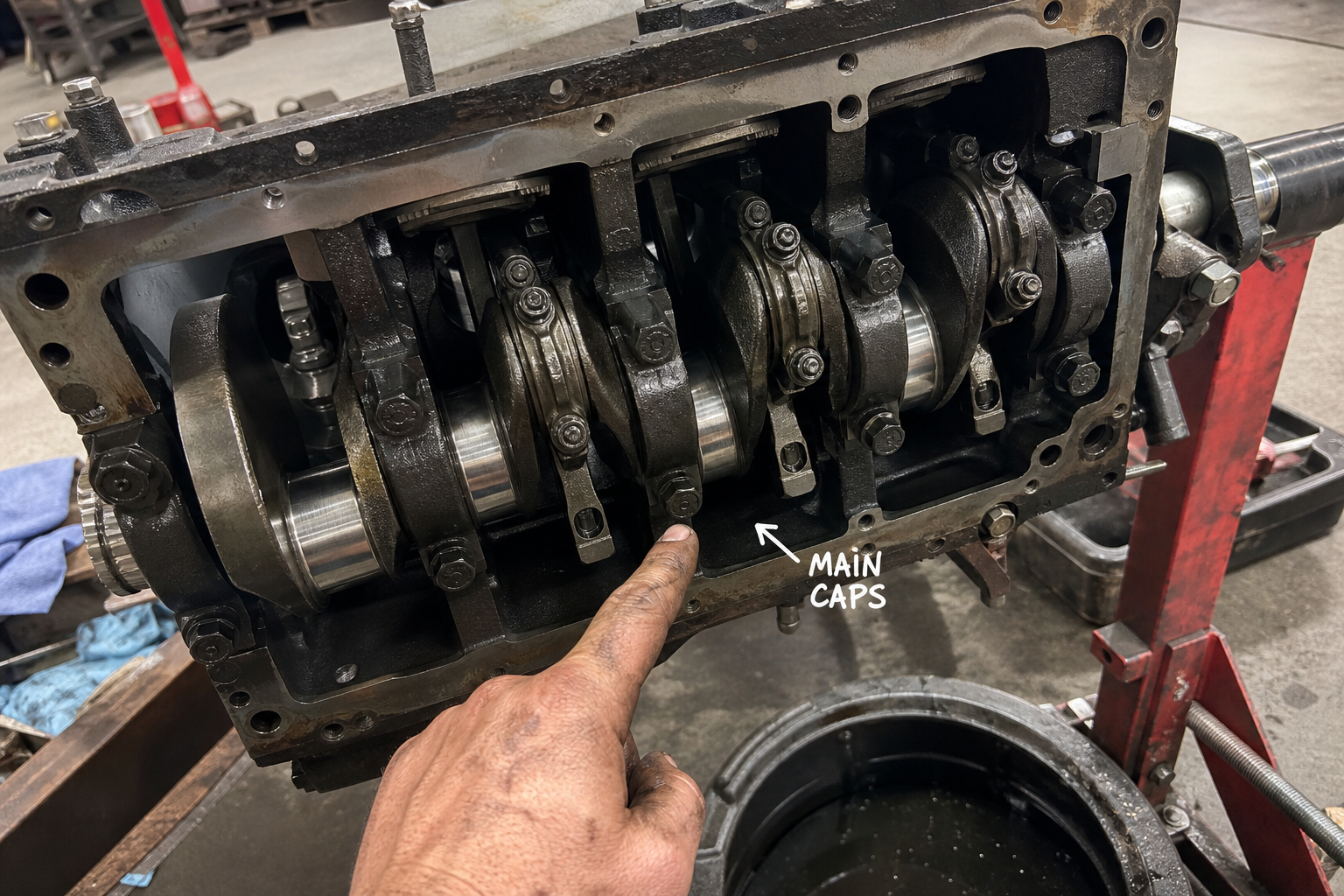
Viewed from below, the main caps support the crankshaft within the block structure.
The cylinder block (https://en.wikipedia.org/wiki/Cylinder_block) sits at the foundation of any internal combustion engine, serving as both the structural anchor and the housing for most moving parts. Unlike bolt-on components such as heads or intake manifolds, the block contains the majority of the engine’s load-bearing architecture and fluid passages. Understanding what lives inside the block—and how each piece connects—matters when diagnosing noise, planning a rebuild, or sourcing replacement parts.
This article maps the physical components contained within or mounted directly to the cylinder block, from the outer casting to the internal bearings and passages that keep everything lubricated and cooled.
Key Takeaways
- The block casting forms the crankcase, cylinder bores, and main bearing supports in a single rigid structure
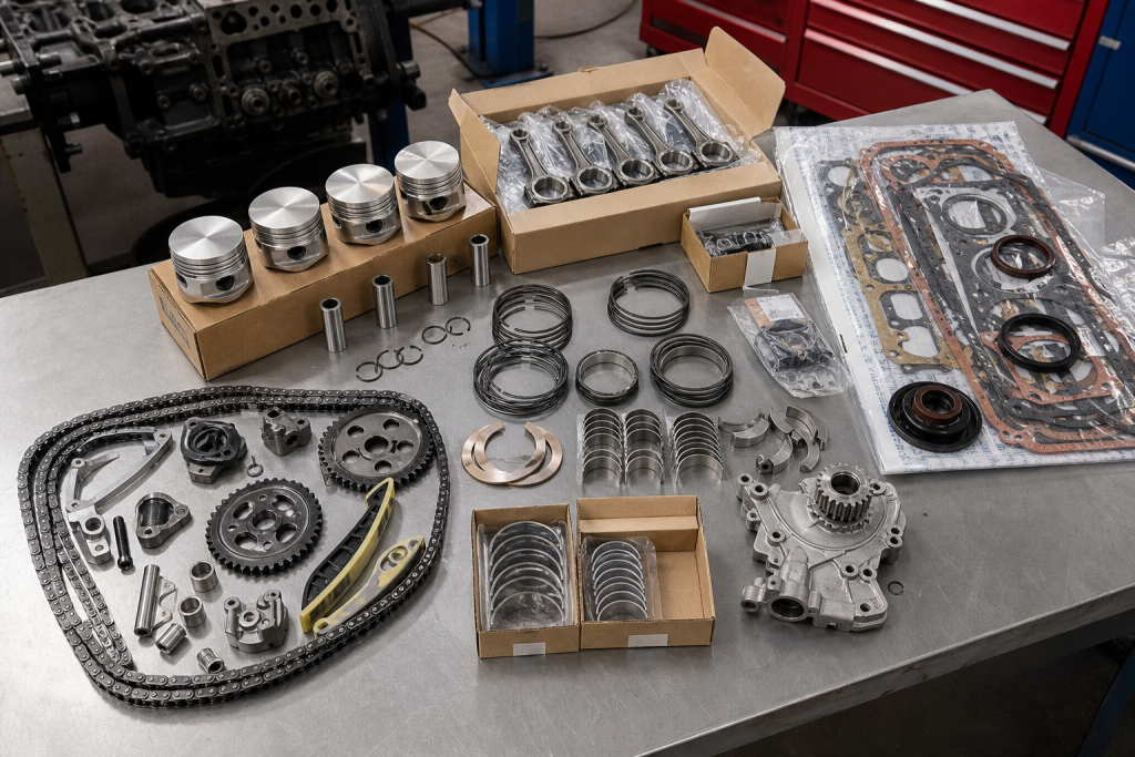
- Pistons, connecting rods, and crankshaft bearings operate inside the block’s crankcase cavity
- Cylinder liners can be cast-in or pressed sleeves depending on block design
- Internal oil galleries and coolant jackets run through the block casting to supply moving parts and manage heat
- Freeze plugs, main caps, and crankshaft supports are block-mounted parts that require correct torque and material specs during assembly
The Block Casting Structure
The cylinder block casting is a single piece of cast iron or aluminum that defines the engine’s physical footprint. It contains vertical cylinder bores arranged in inline, V, or flat configurations, with a lower crankcase cavity that houses the rotating assembly. The casting also integrates mounting bosses for accessories, threaded holes for head bolts, and internal passages for fluids.
Material choice affects durability:
|
Material |
Weight |
Thermal expansion |
Typical use |
|
Cast iron |
Heavy |
Lower |
Diesel, heavy-duty gas engines |
|
Aluminum |
Light |
Higher |
Performance gas engines, modern passenger vehicles |
Cast iron blocks handle higher cylinder pressures and resist wear better in high-mileage applications. Aluminum blocks save weight but require iron or steel cylinder liners to prevent bore wear, since aluminum is too soft for direct piston contact.
Cylinder Bores and Liner Systems
Each cylinder bore is a precision-machined cavity where the piston travels. Bore diameter and stroke length determine engine displacement. The bore surface must maintain a cross-hatch finish for oil retention and ring sealing.
Three liner configurations exist:
- **Cast-in bores** – Cylinder surface is machined directly into the block casting. Common in cast iron blocks.
- **Pressed-in dry liners** – Steel sleeves pressed into the block, no coolant contact. Used when bore wear is excessive or for performance builds.
- **Wet liners** – Replaceable sleeves with direct coolant contact on the outer diameter. Easier to service but require proper sealing at top and bottom.
Wet liners use O-rings or sealing rings at each end to prevent coolant from entering the crankcase. Dry liners rely on interference fit and do not contact coolant. When replacing liners, check casting dimensions and liner protrusion above the deck surface to ensure proper head gasket sealing.
Crankcase and Main Bearing Support Structure
The crankcase is the open cavity below the cylinders where the crankshaft rotates. It encloses the connecting rods, crankshaft counterweights, and oil return paths. The crankshaft (https://en.wikipedia.org/wiki/Internal_combustion_engine) rides on main bearings, which are clamped between the block’s lower bearing saddles and removable main bearing caps.
Main bearing caps bolt to the block from underneath and secure the crankshaft in place. Each cap contains half of the bearing shell, with the other half seated in the block saddle. Caps are numbered and must be reinstalled in the correct position and orientation. Mixing caps or reversing them causes misalignment and bearing failure.
Some blocks use a full-length bedplate instead of individual caps. The bedplate is a single casting that bolts to the entire length of the block, improving crankshaft support rigidity. Bedplate blocks are common in diesel and high-output gas engines.
Pistons, Connecting Rods, and Wrist Pins
Pistons slide up and down inside the cylinder bores, converting combustion pressure into linear motion. Each piston connects to the crankshaft through a connecting rod, which pivots at both ends. The small end attaches to the piston via a wrist pin (also called a piston pin), and the big end clamps around a crankshaft rod journal.
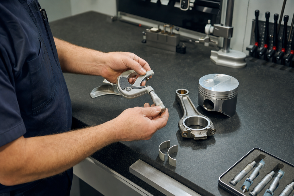
Connecting rod bearing shells line the big end and require precise clearance. Too tight causes seizure; too loose allows oil pressure loss and knock. Bearing clearance is checked with Plastigage or a micrometer during assembly.
Wrist pins can be:
- **Full-floating** – Pin rotates in both piston and rod, held by circlips
- **Press-fit** – Pin is pressed into the rod small end, rotates only in the piston
Press-fit pins require a pin press and temperature control for installation. Full-floating pins are easier to service but need intact circlips to prevent pin migration.
Main and Rod Bearing Shells
Bearings inside the block are thin-wall steel shells with a soft bearing material bonded to the back. They do not rotate; instead, the crankshaft journals spin against the bearing surface with a film of pressurized oil in between.
Bearing identification:
- **Main bearings** – Support crankshaft main journals in the block saddles and caps
- **Rod bearings** – Support crankshaft rod journals at the connecting rod big ends
- **Thrust bearing** – One main bearing position includes thrust washers to control crankshaft end play
Bearings are sized by inside diameter and width. Undersized bearings are available for reground crankshafts. Each bearing set includes upper and lower halves; the upper half often has an oil feed hole aligned with the block’s oil gallery.
Oil Galleries and Lubrication Passages
Oil galleries are drilled passages inside the block casting that distribute pressurized oil from the oil pump to the crankshaft, camshaft (in cam-in-block designs), and lifter bores. The main oil gallery typically runs along one side of the block, with branch passages feeding each main bearing saddle.
Oil flow path:
- Oil pump draws from sump through pickup tube
- Pump output feeds main gallery through block casting
- Gallery branches feed main bearings via drilled passages
- Crankshaft internal drillings transfer oil to rod bearings
- Oil squirters or rod bearing splash lubricates piston pins and cylinder walls
Plugs seal the ends of drilled passages. Missing or loose gallery plugs cause catastrophic oil pressure loss. During a rebuild, verify all gallery plugs are tight and seated. Some blocks use pressed-in cups; others use threaded pipe plugs with sealant.
Coolant Jackets and Water Passages
Coolant jackets surround the cylinder bores and combustion chambers, carrying coolant between the block and cylinder head. The block casting includes inlet and outlet ports, along with vertical passages that align with head gasket openings.
Coolant flow control:
- **Bypass passages** allow coolant to circulate through the block when the thermostat is closed
- **Core plugs** (freeze plugs) seal casting sand core holes from the manufacturing process
- **Block drain plugs** permit complete coolant evacuation for service
Freeze plugs are shallow cups pressed into holes on the side of the block. Despite the name, their primary function is sealing core holes, not preventing freeze damage. Corroded or loose plugs leak coolant and must be driven out with a punch, then replaced with new cups and sealant.
Freeze Plugs and Core Hole Sealing
Freeze plugs, also called expansion plugs or core plugs, seal openings left by sand cores during the casting process. They are not designed to pop out and prevent freeze damage—that is a secondary benefit. Plugs corrode from the inside due to coolant chemistry or external rust.
Replacement procedure:
- Punch a hole in the center of the old plug with a drift
- Pry out the plug without damaging the casting bore
- Clean the bore with a wire brush and solvent
- Coat the new plug’s outer edge with sealant (not the entire cup)
- Drive the plug in squarely until it seats flush or slightly recessed
Plugs are available in steel, brass, and rubber expansion types. Rubber plugs install by tightening a center bolt, which expands the rubber body. They seal easier but are less durable than steel cups.
Block Deck Surface and Head Bolt Bosses
The deck surface is the flat machined face at the top of the block where the cylinder head bolts down. It must be flat within a few thousandths of an inch to maintain head gasket sealing. Warpage, corrosion, or improper resurfacing causes compression leaks and coolant mixing.
Head bolt holes thread into reinforced bosses cast into the block. Damaged threads strip easily during head bolt torque, especially in aluminum blocks. Helicoil or TimeSert thread repairs restore clamping force. Some blocks use through-bolt designs where studs or bolts pass through the block and thread into the bedplate or main caps, increasing structural rigidity.
FAQs
Can you hone cylinders without removing the crankshaft?
No. Proper honing requires removing the crankshaft and pistons to prevent abrasive contamination from entering bearings and oil passages. Honing generates metal particles that must be completely flushed from the block before reassembly.
What causes cylinder liner movement in wet-sleeve blocks?
Improper liner protrusion, damaged O-rings, or incorrect torque on the cylinder head allow liners to shift or lift under combustion pressure. Liners must protrude a specified amount above the block deck to compress the head gasket and seal properly.
Are main bearing caps interchangeable between cylinders?
No. Caps are machined in position with the block and numbered sequentially. Installing a cap in the wrong location or backwards causes bearing misalignment and immediate failure. Always match cap numbers to their corresponding saddles.
How do you measure bearing clearance without Plastigage?
Use an outside micrometer to measure crankshaft journal diameter, then measure bearing inside diameter with a bore gauge or inside micrometer. Subtract journal diameter from bearing inside diameter to get oil clearance. Typical clearance is 0.001–0.003 inches for most engines.
Conclusion
The cylinder block houses the majority of an engine’s structural and rotating components within a single casting. From the precision-machined cylinder bores to the internal oil galleries and coolant passages, each part of the block serves a specific role in supporting combustion, managing heat, and delivering lubrication. Recognizing what components are block-mounted versus externally attached helps when sourcing parts, diagnosing mechanical issues, or planning a rebuild sequence. Main bearing caps, cylinder liners, and internal passages all require correct installation procedures and torque specifications to maintain proper clearances and prevent fluid leaks or component failure.