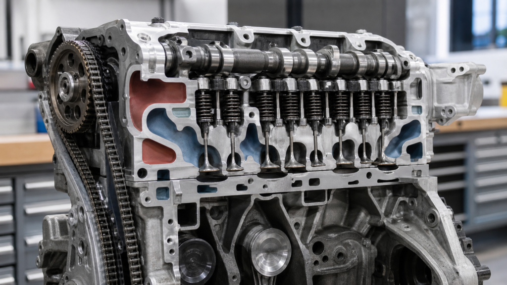
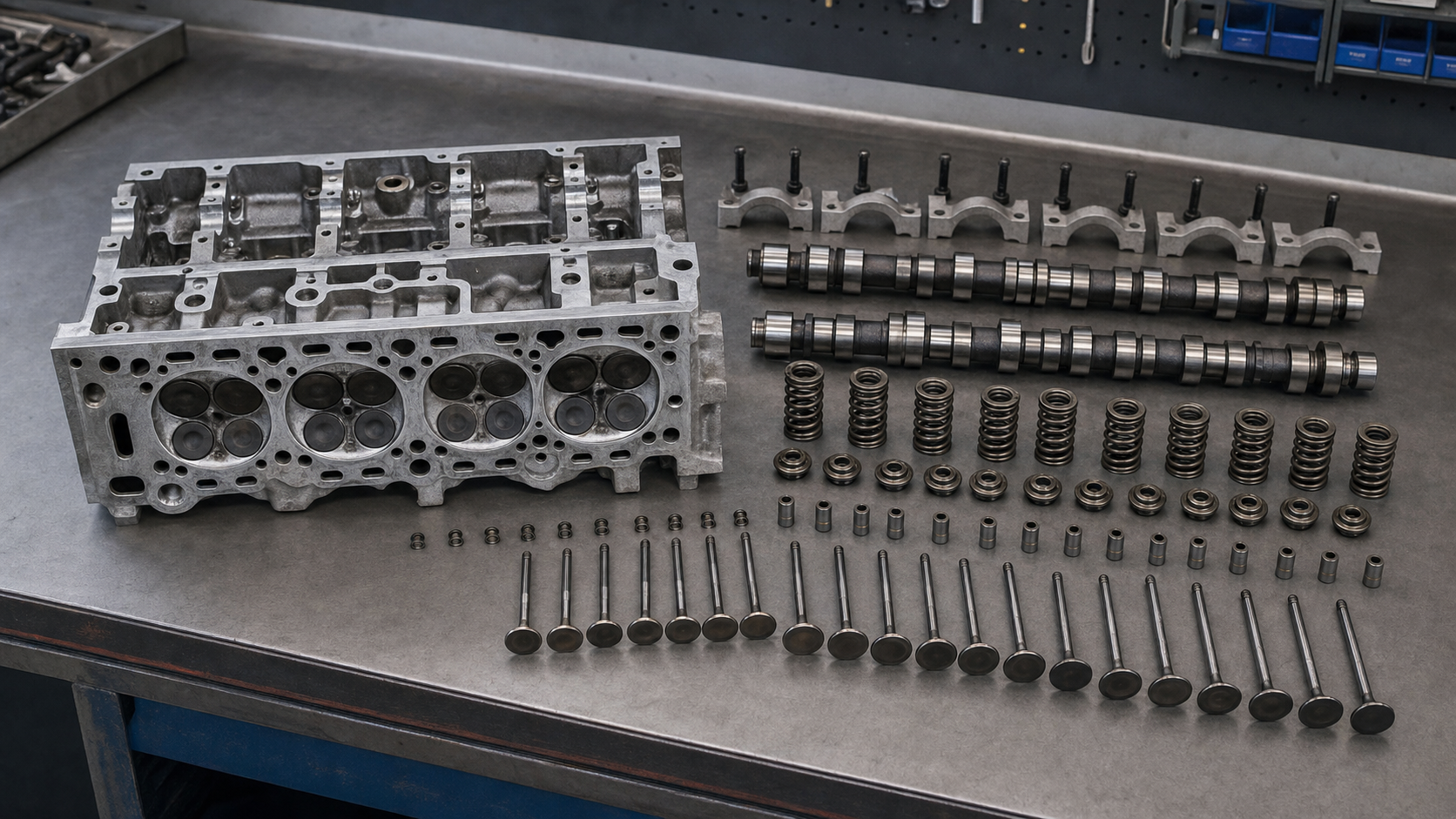
The cylinder head organizes components that control airflow into and out of each combustion chamber. The casting provides intake and exhaust ports, coolant jackets, and oil galleries. Valves, seats, guides, seals, springs, and retainers bolt or press into those passages. Camshafts, rockers, lifters, and cam supports attach above. A head gasket seals the fire deck to the block below. Sensors, plugs, injectors, and other hardware mount to threaded bosses. This article follows air from the intake port through the chamber and out the exhaust port, identifying each cylinder head part and explaining how flow paths determine inspection priorities.
Key Takeaways
- The cylinder head casting defines four main flow paths: intake air, exhaust gas, coolant, and oil
- Valves, seats, guides, and springs control when and how the chamber opens to intake and exhaust ports
- Camshafts, rockers, and lifters convert rotating motion into valve lift; wear surfaces depend on oil pressure and temperature control
- The head gasket and fire deck seal combustion pressure and separate coolant from oil; surface finish and flatness specifications come from the gasket supplier
- Inspection maps check each flow path separately: compression or leak-down test for chamber sealing, pressure test for coolant and oil, visual or dye check for cracks
Read the Cylinder Head through Four Flow Paths
Place a bare cylinder head casting beside a fully assembled head. The casting is a three-dimensional maze of ports, jackets, and galleries. Installed into that structure are removable parts—valves, seats, guides, springs, cam components—that open and close flow paths at specific intervals.
Four main flows run through every cylinder head:
- Intake air enters through the intake port, passes the open intake valve, and fills the combustion chamber
- Exhaust gas exits the chamber through the open exhaust valve and leaves via the exhaust port
- Coolant circulates through water jackets surrounding the chambers and exhaust ports, absorbing heat
- Oil flows through drilled galleries to lubricate cam bearings, rocker pivots, valve stems, and lifter bores
Each flow path crosses or contacts the others at controlled boundaries. The head gasket separates coolant from oil and seals combustion pressure. Valve seals prevent oil from entering the intake or exhaust port. Plug threads isolate coolant jackets from combustion chambers. Understanding cylinder head parts means identifying which component controls each boundary and which failure mode appears when a boundary breaks.
The Casting: Deck, Chambers, Ports, Jackets, and Galleries
The cylinder head casting is the permanent structure. Cast iron and aluminum alloy are the two common materials; the choice affects thermal expansion, machinability, and repair limits.
The casting includes:
Fire deck: the machined flat surface that mates to the block and forms the top of each combustion chamber when the gasket is clamped between the two surfaces.
Combustion chambers: pockets milled or cast into the deck that shape the compression volume. Chamber geometry affects turbulence, quench area, and detonation resistance.
Intake ports: passages that route air or air-fuel mixture from the intake manifold flange to each chamber. Port shape, cross-sectional area, and surface finish influence flow volume and velocity.
Exhaust ports: passages that carry spent combustion gas from each chamber to the exhaust manifold flange. Exhaust ports run hotter than intake ports and often have smaller cross-sections.
Coolant jackets: cavities surrounding the chambers and exhaust ports that circulate liquid coolant. Jackets connect to block passages through holes in the gasket and head.
Oil galleries: drilled or cast passages that deliver pressurized oil to cam bearings, rocker shafts, lifter bores, and valve guides. Galleries connect to block oil passages through the gasket and head bolt holes or separate feed tubes.
Coolant jackets and oil galleries are hidden inside the casting. Their condition cannot be inspected visually after assembly. A cracked coolant jacket may leak coolant into oil galleries, into a combustion chamber, or externally. A blocked oil gallery starves downstream bearings or guides. Pressure testing the coolant system and checking oil flow at each journal are the ways to confirm internal passage integrity before final assembly.
The fire deck surface finish and flatness must meet the head gasket specification. Gasket manufacturers publish maximum allowable warpage and surface roughness for their products; these limits vary by gasket type, material, and thickness. A warped deck or rough surface finish may let combustion gas blow past the gasket even when bolt torque is correct. Deck resurfacing removes material and changes the installed height of the head, which affects compression ratio, valve-to-piston clearance, and cam timing in some designs. Measure deck flatness with a straightedge and feeler gauge before deciding whether machining is necessary.
Valves, Seats, Guides, Seals, Springs, and Retainers
Valves seal the combustion chamber from the ports until the camshaft commands them to open. Each valve assembly includes:
Valve: a steel stem with a head and face. Intake valves use larger head diameters to maximize flow area. Exhaust valves use heat-resistant alloys and smaller diameters because exhaust gas exits under pressure.
Valve seat: a hardened ring pressed or machined into the port entry. The valve face seals against the seat angle when closed. Seat width, angle, and concentricity control sealing and heat transfer from the valve to the head.
Valve guide: a bronze or cast-iron sleeve that supports the valve stem and keeps it aligned with the seat. Guide-to-stem clearance must stay within specification or the valve will wobble, leak, or stick.
Valve seal: an elastomer or Teflon ring that clamps to the valve stem or guide top. It meters the oil film on the stem and prevents excess oil from being drawn into the port during the intake stroke or blown out during exhaust.
Valve spring: one or two coil springs that push the valve closed and keep the lifter or rocker in contact with the cam lobe. Spring rate, installed height, and coil bind clearance are specified to prevent float at high RPM.
Retainer and keepers: a steel cup (retainer) and split wedges (keepers) that lock the spring to a groove near the valve stem tip. Worn grooves or weak keepers let the valve drop into the chamber.
Valve seat recession is a common wear mode on engines that ran leaded fuel and were later converted to unleaded. Lead provided a thin lubricant layer; without it, the exhaust valve hammers the seat and gradually sinks deeper into the head. Modern heads use hardened seat inserts to resist recession. When rebuilding or machining a head, measure installed valve height—the distance from the valve head to the spring seat—to confirm the seat has not recessed beyond the service limit. If the valve sits too deep, the spring loses preload and the valve may not close fully at high RPM.
Valve guide wear shows up as oil consumption and blue smoke. A worn guide lets the valve tilt off-center, which accelerates seat wear and may cause the seal to tear. Measure stem-to-guide clearance with a dial bore gauge or by checking stem rock with a dial indicator while the valve is installed. Replace guides when clearance exceeds the manual limit for your specific engine family.
Spring inspection covers three measurements: free length, installed height, and pressure at a specified compressed length. Comparing free length to the service manual identifies springs that have sagged from heat or fatigue. Installed height confirms the spring seat machining and shim stack are correct. Pressure testing with a spring tester verifies the spring still delivers the specified load at valve lift. A weak spring causes valve float—the valve bounces off its seat instead of following the cam profile—which produces erratic combustion and may allow piston contact.
Camshafts, Rockers, Lifters, and Cam Supports
The camshaft converts crankshaft rotation into valve lift. Overhead cam designs place the camshaft in the cylinder head; pushrod designs mount the camshaft in the block and use pushrods to transfer motion to rockers in the head. Both arrangements include wear surfaces that depend on pressurized oil.
Overhead cam components inside the head:
Camshaft: a hardened steel shaft with eccentric lobes that lift the valves directly or through rocker arms. Cam journals run in bearing surfaces machined into the head or in separate bearing caps.
Cam bearings or bearing caps: split caps or full-circle bearings that position the cam and carry radial and thrust loads. Oil holes in the bearings feed each journal.
Lifters or followers: flat or roller elements that ride on the cam lobes. Direct-acting designs push directly on the valve stem, while rocker designs pivot between the cam and valve.
Rockers: levers that change the direction or ratio of cam lift. Rocker shafts or hydraulic lash adjusters support the pivot point.
Timing components: the cam is driven by a chain, belt, or gear from the crankshaft. The head often includes chain guides, tensioners, or gear mounts.
Pushrod engine components in the head are simpler:
Rocker arms: levers that pivot on a shaft or stud, with one end pushed by the pushrod and the other end pushing the valve stem.
Rocker shaft or studs: the pivot support, fed by an oil passage drilled through the head.
Pushrod guides or passages: holes or tubes that guide the pushrods from the lifter valley in the block to the rocker.
Cam lobe wear appears as a flattened or grooved surface where the lifter rides. Worn lobes reduce valve lift and duration, which lowers power and may cause misfires at idle. Measure lobe height with a micrometer and compare to the unworn lobe specification in your service manual. The acceptable wear limit varies by engine design.
Rocker wear shows up at the valve stem contact pad, the cam contact face, or the pivot bore. Grooved or pitted contact surfaces indicate insufficient oil supply or contaminated oil. Check oil gallery pressure at the rocker shaft before replacing the rocker; low pressure points to a blocked gallery, worn oil pump, or incorrect assembly. When replacing rockers, inspect the mating surfaces on the valve stem tip and cam lobe for transfer wear.
Cam bearing clearance and alignment are measured with Plastigage or a dial bore gauge. Excessive clearance lets the cam whip, which accelerates lobe wear and may cause timing chain or belt problems. Insufficient clearance—caused by bearing misalignment, incorrect cap torque, or debris—starves the journal of oil and leads to seizure. Follow the service manual procedure for cap installation order and torque sequence; many overhead cam designs call for tightening caps in multiple steps to avoid distorting the bearing bores.
Head Gasket, Fire Deck, Bolts, and Sealing Surfaces
The head gasket seals four boundaries simultaneously: combustion pressure between the chamber and the outside world, coolant between the head and block jackets, oil between the head and block galleries, and coolant from oil where those passages cross. Gasket design depends on material, thickness, and clamping method.
Multi-layer steel (MLS) gaskets use several thin stainless steel layers with silicone or Viton coatings. MLS gaskets need smooth surface finishes and flat decks. They tolerate higher cylinder pressures and less re-torque than composite gaskets. MLS gaskets are standard on modern aluminum heads and turbocharged engines.
Composite gaskets use a fiber or graphite core with metal or elastomer fire rings. They conform to rougher surfaces and tolerate minor warpage better than MLS. Composite gaskets are common on older cast-iron engines and low-boost applications.
Head bolt or stud torque creates the clamping force that keeps the gasket compressed. Torque-to-yield (TTY) bolts stretch during installation and must be replaced each time the head is removed. Re-using a TTY bolt reduces clamping force and increases the risk of gasket failure. Non-TTY bolts can be re-used if they pass a length check and thread inspection. Follow the service manual torque sequence and specification; many modern engines use torque-plus-angle tightening, where the final step is an angular rotation rather than a torque value.
Deck flatness is measured with a precision straightedge and feeler gauge at multiple points across the fire deck. The maximum allowable warpage is specified by the gasket manufacturer and varies by gasket type and engine design. Warpage beyond the limit calls for machining to restore flatness. Removing material from the deck lowers the head, which advances cam timing on engines with belt-driven overhead cams and reduces valve-to-piston clearance. Check piston-to-valve clearance with clay or a dial indicator after machining; insufficient clearance causes contact and valve or piston damage.
Surface finish affects gasket sealing. MLS gaskets need a smooth, consistent finish produced by milling or grinding. Belt sanding or coarse machining leaves grooves that let combustion gas blow past the fire ring. Composite gaskets tolerate rougher finishes but still need flat surfaces. Measure surface finish with a profilometer if the gasket specification lists a roughness value; visual inspection alone cannot confirm the finish meets the requirement.
Sensors, Plugs, Injectors, and Attached Hardware
Several components mount to threaded bosses or machined flats in the cylinder head casting:
Spark plugs or glow plugs thread into the chamber and ignite the air-fuel mixture or preheat the chamber. Plug reach, thread size, and heat range must match the engine specification.
Fuel injectors mount in the intake port (port injection) or chamber (direct injection). Injector O-rings or seals prevent fuel and air leaks. Incorrect sealing causes rough idle, fuel odor, or fires.
Coolant temperature sensor threads into a coolant jacket passage and reports temperature to the engine control module. Sensor location affects the reading, so replacement sensors must install in the same boss.
Camshaft position sensor mounts near the cam timing gear or reluctor wheel. It reports cam angle to synchronize fuel injection and ignition. Sensor air gap and alignment are critical for reliable signals.
Intake and exhaust manifolds bolt to the port flanges with gaskets. Port misalignment between the head and manifold creates turbulence and flow loss. Porting the head without matching the manifold wastes the work.
Valve cover seals the top of the head to contain oil splash. Valve cover gaskets and grommets must be replaced during head service to prevent leaks.
Spark plug thread repair is a common head service task. Aluminum heads are prone to stripped plug threads from over-torquing, cross-threading, or corrosion. Helicoil or Time-Sert inserts restore thread strength, but installation demands precise drilling and tapping to maintain plug reach and avoid interference with the piston crown. Measure installed plug reach after insert installation and compare to the original specification.
Injector bore reconditioning addresses sealing problems in direct-injection heads. Carbon buildup or corrosion on the injector sealing surface lets combustion gas blow past the seal. Cleaning and honing the bore restores the seal, but excessive material removal changes injector protrusion and may affect spray pattern. Follow the service manual bore diameter and finish specification.
Cylinder Head Parts Inspection Map
A complete cylinder head inspection checks each flow path and sealing surface separately. The inspection map must document findings and compare them to service limits before approving repair or replacement.
Combustion sealing inspection:
- Perform a compression test or leak-down test on each cylinder before removing the head
- After removal, inspect the fire deck for cracks, erosion, and corrosion at coolant passages
- Measure deck flatness with a straightedge and feeler gauge at multiple locations: diagonally corner to corner, lengthwise along each edge, and across the center
- Check the head gasket for failure patterns—blown areas indicate local overheating, erosion, or insufficient clamping
Valve train inspection:
- Measure valve stem-to-guide clearance with a dial bore gauge or indicator
- Check valve seat width, concentricity, and recession with a seat gauge or dial indicator
- Inspect valve faces for pitting, burning, or cupping; measure stem tip wear
- Test valve spring free length, installed height, and pressure at specified lift
- Measure cam lobe height and journal diameter; compare to unworn specifications
- Check rocker arm wear at the valve stem pad, cam contact, and pivot bore
Coolant system inspection:
- Pressure-test the coolant jacket with the head removed; cap all openings and apply test pressure according to your service manual
- Inspect for external leaks and internal cracks; dye penetrant or magnetic particle inspection reveals hairline cracks invisible to the eye
- Check core plug condition and coolant passage cleanliness; rust or scale buildup restricts flow and causes localized overheating
Oil system inspection:
- Blow compressed air through each oil gallery and confirm flow at each journal or rocker feed point
- Inspect cam bearing bores and rocker shaft bores for scoring, discoloration, or out-of-round wear
- Check oil gallery plug torque or stake condition; loose plugs cause pressure loss
Hardware inspection:
- Check head bolt or stud threads for damage, corrosion, or stretching; measure bolt length and compare to service limit for TTY bolts
- Inspect spark plug threads for stripping or corrosion; measure thread engagement depth
- Test injector bore sealing surfaces for carbon buildup or erosion; measure bore diameter if direct-injection
Failed components must be replaced before reassembly. Marginal findings—measurements within specification but approaching the limit—should be documented and monitored at the next service interval. Northampton Motorsport organizes replacement parts by valvetrain and camshaft categories, which helps match inspection findings to the correct replacement component. CPL Racing provides additional cylinder head technical information for performance applications.
FAQs
Can a cylinder head be repaired if it has a crack?
Repair depends on crack location, length, and whether it crosses a sealing surface. Cracks between valve seats or in non-critical casting areas can be repaired with pinning, welding, or metal stitching if the crack is stable and not near a coolant or oil passage. Cracks crossing the fire deck, through a coolant jacket, or between a chamber and oil gallery are typically unrepairable because welding distorts the sealing surface and weakens the casting structure. Pressure testing after repair confirms whether the crack has been sealed; a persistent leak means the head must be replaced.
How do you know when valve guides need to be replaced instead of just reamed?
Measure stem-to-guide clearance and compare to the service limit. If clearance exceeds the limit, check the guide bore wear pattern. Uniform wear around the entire bore can be corrected by reaming to the next oversize and installing an oversize-stem valve. Tapered, bell-mouthed, or scored bores indicate the guide has lost dimensional control and must be replaced. After guide replacement, the seat must be re-cut because the seat and guide are concentric; changing the guide changes the valve centerline.
What happens if you install a head gasket on a warped deck?
The gasket will not seal uniformly. Areas where the deck is high will compress the gasket fully, but areas where the deck is low will leave gaps that let combustion gas, coolant, or oil leak. Warpage beyond the gasket manufacturer’s specification calls for machining. Installing a thicker gasket does not compensate for warpage; it only lowers compression and may introduce valve-to-piston clearance problems.
Do overhead cam and pushrod cylinder heads use the same inspection process?
The combustion sealing, coolant, and oil gallery checks are identical. The difference is in the valvetrain inspection. Overhead cam heads need cam bearing bore measurement, lobe height checks, and timing component inspection. Pushrod heads need rocker stud or shaft torque checks and pushrod straightness measurement. The valve, seat, guide, spring, and retainer inspection is the same for both designs.
Why does the service manual specify different torque sequences for different engines?
Head bolt torque sequence controls how clamping force is distributed across the fire deck. Incorrect sequence causes uneven gasket compression, which leads to leaks or warping. The sequence is designed around the head bolt pattern, chamber locations, and deck stiffness. Starting at the center and working outward in a spiral pattern is common, but some engines use a different sequence to avoid distorting thin-wall castings or to equalize coolant jacket pressure. Follow the manual sequence for your specific engine model.
Conclusion
Cylinder head parts are organized around four flow paths—intake, exhaust, coolant, and oil—and the sealing surfaces that separate them. Inspection starts with a pressure test and flatness check to confirm the casting and fire deck are sound. Valve, seat, guide, and spring measurements verify the combustion seal and valvetrain control. Cam and rocker checks confirm lubrication and timing are within specification. Before ordering replacement parts or approving a quote, compare inspection findings to service limits in the engine manual and confirm the scope includes all wear items. A complete parts list cross-referenced to the inspection map prevents incomplete repairs and helps the rebuilt head meet the original sealing and flow specifications. Easyrider, TradeIndia, and Allied Motor Parts offer additional cylinder head parts for specific applications.