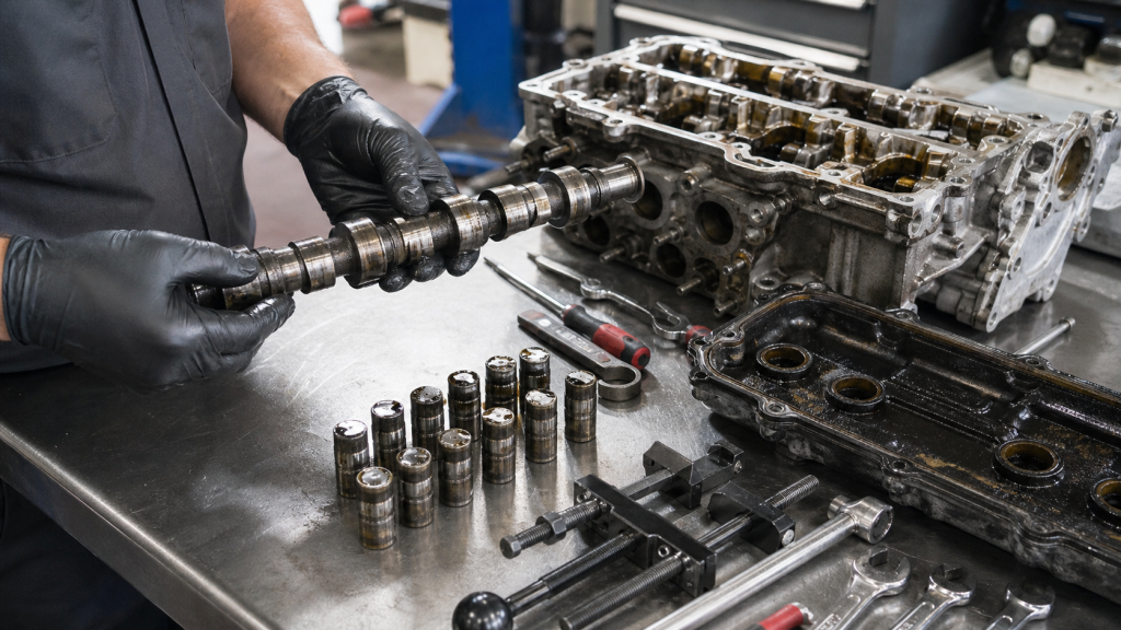
A cylinder head cannot be reliably checked for cracks while assembled, covered in carbon, or still mounted to the engine block. Cracks in critical areas—valve seats, combustion chambers, coolant passages, and exhaust ports—remain hidden under deposits, valve hardware, and injector sleeves until the head is fully disassembled and cleaned. Machine shops reject visual-only inspections because many casting defects, thermal cracks, and stress fractures are invisible to the eye or masked by surface finish and corrosion. This guide follows a bare cleaned head through the inspection route, explaining how to check a cylinder head for cracks using pressure testing, dye penetrant, and magnetic particle methods, then connecting crack location and material to repair decisions and post-repair verification.
Key Takeaways
- Complete disassembly and chemical cleaning precede crack inspection; assembled or dirty heads hide cracks in valve seats, coolant passages, and combustion chambers.
- Pressure testing the coolant circuit detects through-cracks and porosity; dye penetrant and magnetic particle methods find surface-breaking defects in non-magnetic and ferrous materials respectively.
- Repair method depends on material, crack location, and whether the crack reaches a combustion chamber, coolant passage, or valve seat; cast iron accepts cold pinning and lock-stitching, while aluminum requires welding with controlled heat input.
- Post-repair verification includes repeat pressure testing, flatness measurement, and seat concentricity checks to confirm the repair holds and the head meets assembly specifications.
- Service manuals provide flatness limits, pressure test specifications, and seat dimensions; universal tolerances and generic repair pressures do not exist across engine families.
Clean and Disassemble before Crack Inspection
A crack inspection begins with complete disassembly. Remove all valves, springs, retainers, camshaft carriers, and embedded hardware such as injector sleeves, pre-chamber inserts, and valve guides. Many high-risk cracks form at the junction between dissimilar materials—a press-fit guide, a threaded insert, or a seat insert—and remain invisible until the surrounding hardware is extracted. Cast iron heads tolerate mechanical carbon removal, glass bead blasting, and hot-tank caustic cleaning. Aluminum heads require gentler chemical cleaning to avoid surface etching that masks micro-cracks or creates false indications during dye penetrant testing.
The bare casting exposes the machined deck surface, combustion chamber contours, coolant jacket openings, and valve seat pockets. At this stage, wipe the surface with solvent and inspect under bright light for obvious defects—linear marks between valve seats, radial cracks around guide bores, and hairline fractures extending from bolt holes or coolant ports. Visual inspection catches large obvious failures but misses tight cracks that are closed under ambient conditions, subsurface porosity, and defects filled with carbon or coolant residue. That limitation drives the need for pressure testing and penetrant methods before any repair decision is made.
Visual Inspection and High-Risk Locations
High-risk crack locations concentrate thermal and mechanical stress. In cast iron heads, look for cracks bridging the exhaust valve seats—particularly in diesel and turbocharged applications where peak combustion temperatures create severe thermal gradients. The narrow web between adjacent exhaust valves cracks under repeated thermal expansion. In aluminum heads, cracks often radiate from valve guide bores or seat counterbores where press-fit inserts create stress concentrations during thermal cycling. Spark plug or glow plug bosses are another frequent failure point; cracks extend from the threaded hole into the combustion chamber when threads strip or the boss overheats.
Coolant passages crack at sharp corners, thin sections, and abrupt geometry changes. The casting carries molten coolant at one temperature and combustion gases at another; the thermal gradient produces tensile stress perpendicular to the metal flow direction. Water pump mounting ears, thermostat housings, and coolant crossover tubes crack when casting thickness becomes inadequate or when core shift during manufacturing creates an uneven wall. Bolt holes and stud bores crack when overtorque or corrosion weakens the surrounding material. A machine shop inspection process typically catalogs these zones before moving to instrumented testing.
Pressure Testing the Coolant Circuit
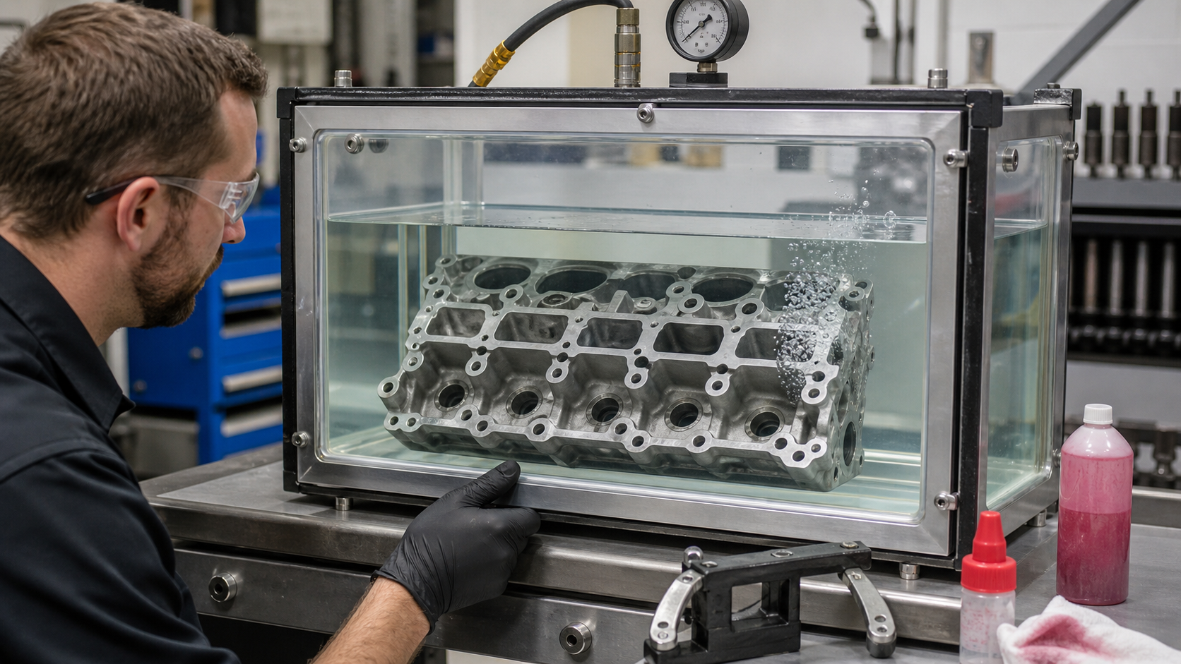
Pressure testing reveals through-cracks and porosity that connect the coolant jacket to combustion chambers, oil passages, or the external environment. The test setup seals all coolant ports with custom plates or expandable plugs, then introduces compressed air or water at a controlled pressure while the head is submerged in a tank or coated with soapy water. Bubbles indicate leak paths. The test pressure must match or slightly exceed normal operating pressure—consult the engine service manual for the exact specification, as automotive systems vary widely.
To pressure test a cylinder head, block all coolant openings with test plates secured by through-bolts or tapered plugs that seal against machined surfaces. Connect a regulated air supply to one remaining port and install a pressure gauge. Submerge the head in a water tank or spray all external and internal surfaces with soapy solution. Bring the pressure to the test value specified in the service manual and hold for at least ten minutes. Watch for bubble streams at valve seats, deck surface cracks, core plug locations, and coolant passage walls. A steady stream indicates a through-crack; intermittent bubbles may point to porosity or a crack that opens under pressure but closes when the stress is removed.
Some shops heat the head before pressure testing to simulate operating thermal expansion. This step opens cracks that remain tight at room temperature and reveals defects that only leak when the engine is hot. If the head passes cold pressure testing but the vehicle history includes coolant loss or combustion gas in the cooling system, request a hot pressure test before committing to a repair quote. Documented test results—pressure value, duration, temperature, and observed leak locations—become part of the inspection record and guide repair method selection.
Dye Penetrant, Magnetic Particle, and Other Methods
Dye penetrant testing finds surface-breaking cracks in any material—cast iron, aluminum, bronze valve guides, or stainless steel inserts. The process applies a liquid penetrant dye to the cleaned surface, allows capillary action to draw the dye into tight cracks, removes excess surface dye, then applies a developer powder that pulls the dye back to the surface as a visible indication. Red dye with white developer provides high contrast under normal light; fluorescent dye requires ultraviolet illumination but detects finer cracks. The method catches narrow defects when surface preparation and dwell time are correct, but it cannot detect subsurface flaws or cracks that do not reach the surface.
Magnetic particle testing applies to ferrous materials only—cast iron and steel heads, not aluminum. The test magnetizes the casting with a yoke or coil, then applies ferromagnetic particles in a liquid carrier or dry powder. Cracks disrupt the magnetic field and concentrate particles at the defect, creating a visible line. Magnetic particle testing detects surface and slightly subsurface cracks and works faster than dye penetrant on cast iron heads with multiple suspected areas. Demagnetization after testing prevents interference with sensors and actuators during reassembly.
Ultrasonic and eddy current testing are specialist methods used for critical applications—marine, aircraft, or racing engines—where subsurface cracks and material thinning must be quantified. These methods require calibrated equipment and trained operators, and shops typically reserve them for high-value cores or liability-sensitive rebuilds. For routine automotive and industrial engine work, pressure testing plus either dye penetrant or magnetic particle inspection provides sufficient coverage.
Repair Options by Material and Crack Location
Repair feasibility depends on whether the crack reaches a sealing surface, a coolant passage, or a combustion chamber. Cracks confined to non-critical areas—such as a cosmetic crack in an external rib or mounting ear—may be left alone if they do not propagate. Cracks that communicate between the coolant jacket and a combustion chamber, between oil and coolant, or between coolant and the external environment require repair or replacement. The material and crack geometry dictate the process.
Cast iron heads accept cold repair methods that do not introduce additional thermal stress. Lock-stitching or pinning installs overlapping metal pins or stitches across the crack, effectively stitching the fracture closed. The method works well for cracks between valve seats, in coolant passages, and around stud holes, provided the crack does not extend into a combustion chamber where high pressure would blow out the pins. Tapered plugs can seal cracked coolant ports if the crack does not reach a sealing surface. Cold repair preserves the original casting microstructure and avoids warpage, but it adds material thickness that may require subsequent machining to restore flatness or seat depth.
Aluminum heads require welding because mechanical fasteners cannot withstand combustion pressure and thermal cycling in a soft alloy. TIG welding with appropriate aluminum filler matches the base alloy and provides a fusion bond, but heat input must be tightly controlled to prevent warpage. Preheat and post-weld stress relief minimize distortion. Some shops use specialized thermal spray welding that deposits material at lower temperatures, reducing the risk of dimensional change. Furnace welding places the entire head in a controlled-atmosphere furnace, allows the repair zone to reach welding temperature uniformly, and cools slowly—eliminating localized distortion at the cost of longer turnaround and higher process expense.
Repair method also depends on crack orientation. A crack parallel to the deck surface may seal adequately after welding or pinning, but a crack perpendicular to the deck that opens under head bolt torque will likely re-crack. When a crack extends through a valve seat insert pocket, the insert must be removed, the pocket repaired, and a new insert installed with interference fit and proper heat treatment. If the crack compromises a machined datum—such as the camshaft bore centerline or the deck surface reference—the head may not return to specification even after successful crack repair, and replacement becomes the better option.
Machining, Seat Work, and Heat-Treatment Concerns
Crack repair adds or rearranges material, and most repair methods introduce residual stress or change local hardness. Pinning raises the surface where pins intersect the deck, requiring deck milling to restore flatness. Welding shrinks the surrounding area and may pull the deck surface out of plane. The service manual specifies maximum material removal, and the cumulative removal from previous resurfacing operations must be checked before machining post-repair. If the head has already been milled to the limit, additional material removal shortens valve stems, reduces compression ratio, and may prevent correct valve timing; in that case, replacement is mandatory.
Valve seat reconditioning follows deck milling. Seats must be concentric to the valve guide within the tolerance specified by the engine manufacturer, and seat width, angle, and surface finish must meet the valve manufacturer’s specification to ensure sealing and heat transfer. If the crack repair involved welding near a seat, the heat-affected zone may have changed hardness, making the seat more prone to recession under load. Shops typically cut new seats after welding, measure concentricity, and verify that the seat insert remains secure. Bronze or ductile iron seat inserts in aluminum heads require interference fits that depend on controlled temperature; if the repair process overheated the pocket, the insert may loosen during operation.
Heat treatment considerations apply primarily to aluminum heads that were welded. Most aluminum cylinder heads are cast in T6 or T7 temper, meaning they were solution heat-treated and artificially aged to achieve target strength and hardness. Welding disrupts the temper in the heat-affected zone, reducing strength substantially. Post-weld heat treatment restores properties but requires furnace equipment and risks warpage if fixturing is inadequate. Not all shops offer post-weld heat treatment, and skipping this step leaves a softer region around the repair that may crack again under service load. Verify whether the quote includes heat treatment before authorizing a weld repair on an aluminum head.
Post-Repair Pressure, Flatness, and Leak Verification
Every repaired head must be pressure tested again after machining and before reassembly. The repeat test uses the same pressure and method as the initial inspection, confirming that the repair sealed the crack and no new leaks developed during machining or handling. If the head fails the post-repair pressure test, the crack either propagated beyond the repaired zone or the repair itself cracked under test pressure. At that point, further repair is rarely cost-effective, and replacement becomes the recommended path.
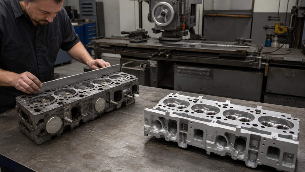
Flatness measurement verifies that the deck surface lies in a single plane within the service manual tolerance. Use a precision straightedge and feeler gauges, or measure with a dial indicator across the deck length and width. Consult the service manual for the flatness limit, as gasoline and diesel engines have different requirements based on compression ratio and combustion pressure. If the head exceeds the flatness limit after repair and machining, it cannot seal reliably, and further milling may exceed the material removal limit. Document the flatness result and compare it to the specification before final assembly.
Additional verification includes seat concentricity, valve guide clearance, and camshaft bore alignment. A seat runout gauge measures how much the seat deviates from the guide centerline; excessive runout causes valve leakage and accelerated wear. Valve guide inside diameter must remain within specification, and guide height must be correct after deck milling. Overhead cam heads require camshaft bore alignment within tight tolerances; if the repair or machining shifted the bores, the camshaft will bind or wear prematurely. These measurements take time but prevent comebacks and secondary damage.
FAQs
Can a cracked cylinder head be driven safely until repair?
Driving on a cracked cylinder head depends on where the crack is and what it connects. A crack between coolant and combustion allows coolant into the cylinder, causing white exhaust smoke, coolant loss, and potential hydro-lock if coolant accumulates overnight. A crack between coolant and oil produces a milky emulsion in the oil or coolant, leading to lubrication failure and bearing damage. A crack in an external rib that does not reach a fluid passage may be cosmetic and drivable, but most cracks that produce symptoms will worsen under thermal cycling. Continued operation risks warping the deck surface, damaging the head gasket, and contaminating the engine oil, turning a repairable head into a replacement case.
How much does cylinder head crack repair cost compared to replacement?
Repair cost depends on material, crack location, and labor rates. Machine shops quote pinning or stitching cast iron heads at different rates than welding aluminum heads due to process complexity and heat treatment requirements. Replacement cost includes the new or remanufactured head, gasket set, head bolts, and labor to swap the assembly. If the crack is isolated and the rest of the head—seats, guides, deck flatness—remains serviceable, repair may represent a fraction of replacement cost. If the head also needs extensive seat work, guide replacement, or multiple machining operations, replacement often provides better value and a warranty. Request a detailed inspection report and compare line-item quotes before deciding.
Does pressure testing detect all types of cylinder head cracks?
Pressure testing detects through-cracks and porosity that connect the coolant jacket to another space, but it misses surface cracks that do not penetrate the casting wall and subsurface cracks that remain isolated. A crack in the deck surface between cylinders may not show during coolant pressure testing if it does not reach a coolant passage, but it will leak combustion gas and cause a head gasket failure. Dye penetrant and magnetic particle testing catch these surface defects. For complete crack detection, use pressure testing to find internal leaks and follow with a surface method to find non-through cracks in critical areas like valve seats and combustion chambers.
Can I repair a cracked aluminum cylinder head with epoxy or sealant?
Epoxy, chemical sealants, and stop-leak additives do not provide a durable repair for cracked cylinder heads. Combustion pressure in modern engines combined with thermal cycling exceeds what adhesive or polymer sealants can withstand. Sealants may temporarily plug a small coolant leak, but they contaminate the cooling system, clog radiator tubes, and block coolant flow to critical areas. Temporary sealants are appropriate only as a get-home measure before proper repair. Permanent repair requires welding for aluminum or mechanical pinning for cast iron, followed by machining and pressure testing to verify the repair.
What causes cylinder head cracks and how can I prevent them?
Cracks form from thermal stress, mechanical overload, or casting defects. Overheating—caused by coolant loss, failed water pump, stuck thermostat, or clogged radiator—creates extreme temperature gradients that exceed the material’s tensile strength. Detonation and pre-ignition generate pressure spikes that hammer the combustion chamber and valve seats. Corrosion from incorrect coolant or lack of coolant maintenance weakens thin sections in the coolant jacket. Overtorquing head bolts or uneven torque sequence concentrates stress around bolt holes. Prevention includes maintaining correct coolant mixture and condition, addressing overheating immediately, using the correct torque sequence and values during assembly, and avoiding sustained detonation or lean combustion that raises peak temperatures.
Conclusion
Checking a cylinder head for cracks requires complete disassembly, thorough cleaning, and multiple detection methods—pressure testing for internal leaks, dye penetrant or magnetic particle inspection for surface defects, and visual examination of high-risk locations around valve seats, coolant passages, and bolt holes. Repair decisions depend on crack location, material, and whether the defect reaches a combustion chamber or sealing surface; cast iron accepts cold pinning while aluminum requires controlled welding and often post-weld heat treatment. After repair, verify the work with repeat pressure testing, flatness measurement, and seat concentricity checks before reassembly. If your inspection reveals cracks in critical areas or the head has already reached its machining limit, request quotes for both repair and replacement, comparing the scope, warranty, and turnaround for each option before committing to a path.