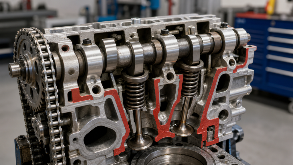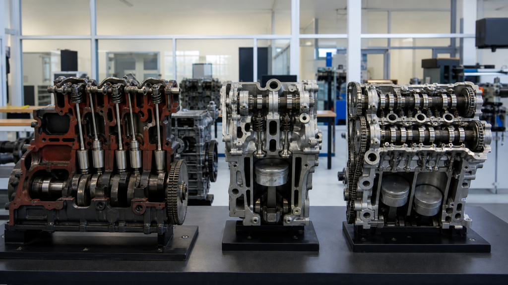
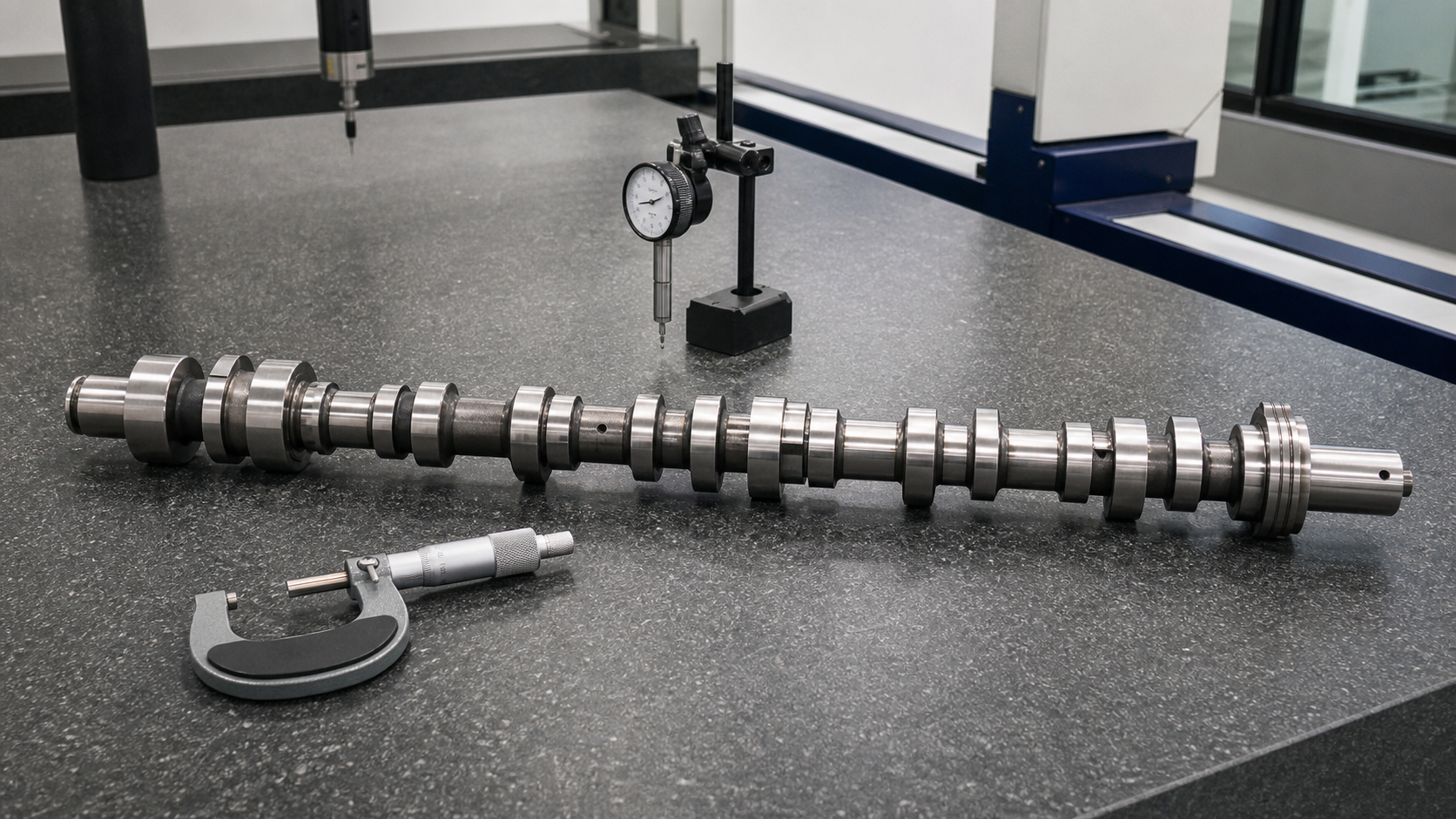
Place an unidentified camshaft on a metrology bench and you will see a long, precision-machined shaft with eccentric lobes, polished journals, gear teeth at one end, and oil passages drilled through multiple bearing surfaces. Each feature serves a specific function: lobes open and close valves, journals rotate inside bearing shells, thrust surfaces control axial movement, drive gears or sprockets synchronize valve timing with the crankshaft, and secondary drives may power distributors, fuel pumps, or position sensors. Identifying camshaft parts by function rather than appearance ensures that inspection, measurement, and replacement decisions address the actual failure mode and the complete scope of related components.
Key Takeaways
- Cam lobes control valve lift and duration through base circle, flank, and nose geometry; measure lobe height and taper to detect wear patterns that affect valve timing and sealing.
- Bearing journals rotate inside plain bearings lubricated by pressurized engine oil; inspect journal diameter, surface finish, and oil-passage alignment to confirm adequate clearance and oil delivery.
- Thrust surfaces and retaining hardware limit camshaft endplay; excessive axial movement can misalign lobes with rocker arms or followers and change valve timing.
- Drive gears, sprockets, and keyways synchronize camshaft rotation with the crankshaft; inspect gear teeth, keyway fit, and timing marks before installation to prevent jumped timing or catastrophic interference.
- Related valvetrain parts—including lifters, rocker arms, pushrods, valve springs, and timing components—must be inspected alongside the camshaft because shared wear patterns indicate correlated failure modes.
Camshaft Diagram Orientation: Drive End to Rear Journal
A functional camshaft diagram starts at the drive end, where the timing gear or sprocket mounts, and moves toward the rear journal, where the thrust surface typically resides. This orientation matches the physical inspection sequence: measure the front bearing journal first, check each lobe bank in firing order, inspect intermediate journals for taper and out-of-round conditions, verify oil-passage alignment, and finish at the rear thrust surface and retaining hardware. The drive end establishes the camshaft’s rotational reference because timing marks on the gear or sprocket align with corresponding marks on the crankshaft gear or chain during installation.
On overhead-cam engines, the camshaft runs horizontally above the cylinder head with lobes pointing downward toward valve stems or rocker arms. On pushrod engines, the camshaft sits in the engine block with lobes pointing upward toward lifters. Both configurations use the same core parts—lobes, journals, thrust controls, and drive features—but the mounting location changes bearing-bore alignment tolerances, oil-delivery paths, and the number of journals required to prevent deflection under valve-spring loads.
Walk the camshaft from drive end to rear to understand how each feature contributes to valve timing, lubrication, and load distribution. This sequence ensures that inspection findings correlate with actual operating conditions rather than isolated measurements.
Cam Lobes: Base Circle, Flanks, Nose, and Taper
Each cam lobe consists of a base circle, opening and closing flanks, and a nose. The base circle is the round portion that maintains zero valve lift when the lobe rotates away from the lifter or follower. The flanks are the ramped surfaces that accelerate the lifter upward during the opening phase and decelerate it during the closing phase. The nose is the high point of the lobe, where maximum valve lift occurs. Together, these regions define the camshaft’s lift (vertical distance from base circle to nose), duration (crankshaft degrees during which the valve remains open), and acceleration profile (rate of change in lifter velocity).
Measure lobe height from the base circle to the nose tip using a micrometer or dial indicator. A worn nose reduces peak lift and shortens effective valve duration, limiting airflow into the combustion chamber. Compare each lobe’s height to the service-manual specification and to adjacent lobes on the same camshaft. Variation between lobes indicates uneven wear from inadequate lubrication during cold starts, contaminated oil, misaligned valve springs, or excessive rocker-arm side load.
Inspect the lobe flanks for taper, a condition where one side of the lobe wears faster than the other. Taper usually appears when the lifter bore is out of alignment with the lobe centerline or when the lifter itself does not rotate freely. Some camshaft designs intentionally introduce slight taper on the lobe and a matching crown on the lifter face to induce rotation and distribute wear evenly. Measure taper by taking readings at multiple points across the lobe width and comparing them to the engine manufacturer’s drawing. Excessive taper concentrates contact stress, accelerates wear, and can cause the lifter to seize in its bore.
Check the base circle for scoring, pitting, or flat spots. The base circle experiences lower contact stress than the nose but still depends on continuous oil delivery. If the base circle shows damage, inspect the corresponding lifter, rocker arm, or follower for matching wear patterns that confirm a lubrication failure rather than isolated lobe damage.
Bearing Journals and Oil Passages
Camshaft bearing journals are precision-ground cylindrical surfaces that rotate inside plain bearings pressed or machined into the engine block or cylinder head. Each journal must maintain a controlled oil clearance to form a hydrodynamic oil film that supports the camshaft under valve-spring loads without metal-to-metal contact. The specific clearance range varies by engine family and journal diameter; consult the service manual for the exact specification. Excessive clearance allows the camshaft to vibrate and lose timing accuracy; insufficient clearance starves the bearing and causes scuffing or seizure.
Measure journal diameter at multiple points around the circumference and along the journal length using an outside micrometer. Calculate out-of-round by subtracting the minimum diameter from the maximum diameter. Calculate taper by comparing readings taken at each end of the journal. Service manuals specify maximum out-of-round and taper limits; exceeding these limits requires camshaft replacement or journal regrinding followed by undersize bearing installation.
Inspect the journal surface finish under good lighting. A polished, mirror-like surface indicates normal wear. Scoring, discoloration, or dull patches suggest inadequate lubrication, oil contamination, or bearing misalignment. Theengineerspost.com explains that cam bearing journals must maintain precise alignment and surface finish to prevent accelerated wear during high-speed operation.
Check oil passages drilled through the camshaft and journals. These passages deliver pressurized oil from the main oil gallery to each bearing surface and, in some designs, to the cam lobes themselves. Verify that passages are clear by blowing compressed air through the camshaft and observing oil exit points. Blocked passages cause localized oil starvation and rapid bearing failure. Inspect passage entry and exit points for cracks or erosion that can redirect oil flow away from critical surfaces.
Record journal diameter, clearance, and surface condition for each bearing position. Compare findings to service-manual specifications and correlate journal wear with bearing-shell condition, oil-filter contamination, and oil-pressure history to confirm the root cause before ordering replacement parts.
Thrust Control, Nose, Gear, Sprocket, and Key Features
Camshaft thrust control limits axial movement along the shaft centerline. Excessive endplay can shift lobe position relative to lifters or rocker arms, changing valve timing and introducing noise or wear. Most pushrod engines use a thrust plate bolted to the front of the engine block, with a machined surface that contacts a flange or journal on the camshaft. Some overhead-cam engines control thrust with a flanged bearing journal or a retaining cap that captures the camshaft between two surfaces. Measure endplay by installing a dial indicator against the camshaft nose, then prying the shaft forward and backward while recording total travel. Consult the service manual for the endplay specification for your specific engine.
The drive gear or sprocket mounts to the front of the camshaft and meshes with the crankshaft gear or timing chain. On gear-driven systems, inspect gear teeth for chipping, wear patterns, and backlash. Excessive backlash allows the camshaft to oscillate relative to the crankshaft, introducing valve-timing variation under load. On chain-driven systems, inspect the sprocket for wear grooves, bent teeth, or keyway damage. Replace the timing chain and guides whenever replacing the camshaft, because a worn chain can jump timing even with a new sprocket.
Inspect the Woodruff key or keyway that locks the gear or sprocket to the camshaft. The key must fit snugly in both the shaft keyway and the gear keyway without rocking or lateral play. A loose key allows the gear to rotate independently of the camshaft, causing immediate timing loss and potential valve-to-piston contact. A sheared key indicates overload from excessive valve-spring pressure, incorrect assembly torque, or interference during a previous timing event.
Verify timing marks on the gear or sprocket and compare them to marks on the crankshaft gear or chain. Timing marks must align at specific crankshaft positions defined in the service manual. Misalignment by even one tooth can advance or retard valve timing enough to cause rough idle, power loss, or starting failure. Photograph the timing-mark alignment before disassembly and reference the service-manual diagram during installation.
Check the front camshaft nose for thread damage, seal-wear grooves, or impact marks. The nose often carries a bolt that retains the gear or sprocket and may also support a front seal or sensor target. Thread damage requires camshaft replacement unless the threaded section can be repaired with a thread insert approved by the engine manufacturer.
Distributor, Fuel-Pump, and Sensor Drive Features
Some camshafts include additional drive features that power engine accessories or provide position feedback to the engine control module. Older distributor-equipped engines use a distributor drive gear machined into the camshaft or mounted on a separate eccentric lobe. The distributor shaft meshes with this gear, rotating at half crankshaft speed to deliver spark to each cylinder in firing order. Inspect the distributor gear for tooth wear, pitch variation, and axial runout. A worn gear causes erratic ignition timing, misfires, or distributor-shaft failure.
Mechanical fuel-pump drive lobes appear on some pushrod engines as an additional eccentric lobe that actuates a pivoting lever connected to the fuel pump. Measure the lobe’s lift and compare it to the fuel-pump manufacturer’s specification. Insufficient lift reduces fuel-pump stroke and can cause low fuel pressure, even if the pump itself is functional.
Modern engines replace mechanical distributor and fuel-pump drives with electronic sensors that read camshaft position. The camshaft-position sensor target may be a toothed wheel, reluctor ring, or machined slot on the camshaft sprocket or rear journal. The sensor detects this target to determine which cylinder is approaching top dead center on the compression stroke, allowing the engine control module to synchronize fuel injection and ignition. Inspect the sensor target for damaged teeth, rust, or metal debris that can cause missing or erratic position signals. Clean the target with a non-residue solvent and verify sensor air-gap clearance during installation.
Record the condition of all drive features during inspection. Accessory-drive failures often correlate with primary camshaft wear, because both result from the same lubrication or assembly defects. Replacing the camshaft without addressing worn distributor gears or damaged sensor targets leaves partial failure modes active.
Related Valvetrain Parts That Are Not Part of the Camshaft
The camshaft operates inside a valvetrain assembly that includes lifters, pushrods, rocker arms, valve springs, timing chains, and guides. These parts are not part of the camshaft itself, but they share load paths and wear mechanisms that make correlated inspection essential.
Lifters (also called tappets or cam followers) ride on the cam lobes and convert rotational camshaft motion into linear motion that opens the valves. Hydraulic lifters use oil pressure to maintain zero valve lash; solid lifters require periodic adjustment. Inspect lifter faces for wear, scoring, or concave wear patterns that indicate inadequate lubrication or lobe taper. Replace lifters whenever replacing the camshaft, because used lifters wear into their original lobes and may not seat properly on new lobe surfaces.
Rocker arms pivot on shafts or individual studs to transfer lifter motion to the valve stems. Inspect rocker-arm contact surfaces, bushings, and pivot points for wear. Excessive wear changes the rocker ratio and effective valve lift. On overhead-cam engines, rocker arms or finger followers contact the cam lobes directly, making their wear patterns critical to lobe inspection.
Pushrods connect lifters to rocker arms on pushrod engines. Inspect pushrod ends for mushrooming, ball-socket wear, or bending. A bent pushrod indicates valve-spring bind, interference, or incorrect installation during a previous repair.
Valve springs provide the closing force that keeps valves sealed during combustion and maintains contact between lifters and lobes during the base-circle phase. Measure valve-spring installed height and free length. Weak or broken springs allow valve float at high engine speeds, reducing power and causing potential valve-to-piston contact. Replace valve springs and retainers whenever replacing the camshaft in a high-mileage engine.
Timing chains, belts, guides, and tensioners synchronize camshaft and crankshaft rotation. Inspect chain or belt wear, guide-rail damage, and tensioner function. Replace timing components as a set whenever replacing the camshaft, because worn chains can jump timing under load and cause catastrophic valve damage.
Valvetrain inspection must be comprehensive. A single worn component can overload adjacent parts and cause cascade failure even after camshaft replacement.
Inspection Checklist for Each Feature
Use this checklist to document camshaft condition and identify replacement scope:
Cam Lobes
- Measure lobe height from base circle to nose for all lobes; compare to service-manual specification and between lobes
- Check lobe width for taper using measurements at three points across the lobe face
- Inspect flanks and nose for scoring, pitting, or discoloration indicating inadequate lubrication
- Verify base-circle roundness and surface finish
Bearing Journals
- Measure journal diameter at four points around circumference and at each end of the journal
- Calculate out-of-round (maximum diameter minus minimum diameter) and taper (front diameter minus rear diameter)
- Inspect journal surface for scoring, heat discoloration, or dull finish
- Blow compressed air through oil passages and verify flow at all exit points
Thrust Control
- Measure camshaft endplay using dial indicator; compare to service-manual specification
- Inspect thrust plate or thrust journal for wear grooves, scoring, or cracks
- Check thrust-plate bolt holes and mounting surface for damage
Drive Gear or Sprocket
- Inspect gear teeth or sprocket grooves for wear, chipping, or bent teeth
- Measure gear backlash or chain slack; compare to service-manual specification
- Check Woodruff key and keyway fit for looseness or damage
- Verify timing-mark visibility and alignment with crankshaft marks
Sensor and Accessory Drives
- Inspect sensor target teeth or slots for damage, rust, or debris
- Check distributor gear (if present) for tooth wear and axial runout
- Measure fuel-pump lobe lift (if present) and compare to specification
Related Valvetrain Parts
- Inspect lifter faces for wear patterns and compare to corresponding lobe condition
- Check rocker arms, pushrods, and valve springs for wear, damage, or out-of-specification measurements
- Evaluate timing chain, guides, and tensioners for wear and replace as a set with the camshaft
Document all measurements and observations in an inspection report. Compare findings to service-manual limits and correlate wear patterns across multiple components to identify root causes. Present the complete replacement scope—including related valvetrain parts, timing components, and required machine work—in the repair estimate to avoid incomplete repairs and repeat failures.
FAQs
Can I replace just the camshaft without replacing lifters and timing components?
Replacing only the camshaft while retaining used lifters risks accelerated wear because the lifter faces have worn into the old lobe profiles. The lifters may not seat properly on new lobes, creating point-contact stress that causes rapid failure. Similarly, retaining a worn timing chain or stretched timing belt allows the new camshaft to operate with incorrect timing or jump timing under load. Replace lifters, timing chains or belts, guides, and tensioners whenever replacing the camshaft to ensure proper break-in and prevent correlated failures.
How do I identify whether camshaft wear caused the failure or resulted from another component?
Inspect wear patterns on both the camshaft lobes and the corresponding lifters or followers. Uniform wear across all lobes and lifters indicates normal service life or gradual lubrication degradation. Isolated wear on specific lobes suggests misaligned valve springs, bent pushrods, or incorrect rocker geometry affecting only those cylinders. Scoring or heat discoloration on journals points to oil-pressure loss, blocked oil passages, or bearing-shell failure. Review the oil-filter contents, oil-pressure logs, and engine service history to determine whether the camshaft failed first or responded to damage elsewhere in the valvetrain or lubrication system.
What measurements confirm that a used camshaft can be reinstalled after inspection?
Compare all measured lobe heights to the service-manual minimum specification. Verify that journal out-of-round and taper fall below the manual’s maximum limits. Confirm that endplay remains within specification after accounting for thrust-surface wear. Inspect all oil passages for blockages and verify free flow with compressed air. Check that drive-gear teeth, keyways, and timing marks remain undamaged. A camshaft that meets all service-manual specifications for lobe height, journal diameter, surface finish, and oil-passage integrity can be reinstalled with new bearings and lifters, provided the inspection also confirms that related valvetrain parts meet their respective specifications.
Why does lobe taper matter if the lifter face is slightly crowned?
Intentional lobe taper and lifter crown work together to induce lifter rotation, distributing wear evenly across the lifter face and preventing a wear groove from forming in a single location. Excessive taper beyond the design specification overloads one edge of the lifter, concentrating contact stress and accelerating wear. The lifter may stop rotating or develop an off-center wear pattern that contacts only the lobe edge. Measure taper at multiple widths and compare findings to the engine manufacturer’s drawing rather than assuming all taper is intentional.
When does camshaft replacement require machine-shop services beyond parts installation?
Camshaft replacement may require bearing-bore alignment checking, especially in overhead-cam cylinder heads where bearing caps can shift during removal. If new bearings are undersize to accommodate reground journals, the machine shop must verify bearing crush and oil clearance after installation. Pushrod engines with replaceable cam bearings require bearing installation tools and clearance verification. On interference engines, the machine shop should perform a clay check or dial-indicator sweep to confirm valve-to-piston clearance after camshaft installation and timing-mark alignment. Include machine-shop services in the replacement scope estimate when bearing work, interference checking, or journal regrinding is required.
Conclusion
Identifying camshaft parts by function—not just appearance—ensures that inspection findings address the actual failure mode and the complete scope of related components. Walk the camshaft from drive end to rear journal, measuring lobe height, journal diameter, thrust endplay, and drive-feature condition at each position. Document all findings in an inspection report and compare them to service-manual specifications rather than universal limits. Correlate camshaft wear patterns with lifter, rocker-arm, and timing-component condition to determine whether the camshaft failed first or responded to damage elsewhere in the valvetrain. Request a detailed replacement quote that includes the camshaft, lifters, timing components, bearings, and any required machine work, then verify that the quoted scope matches the inspection findings before authorizing repair.