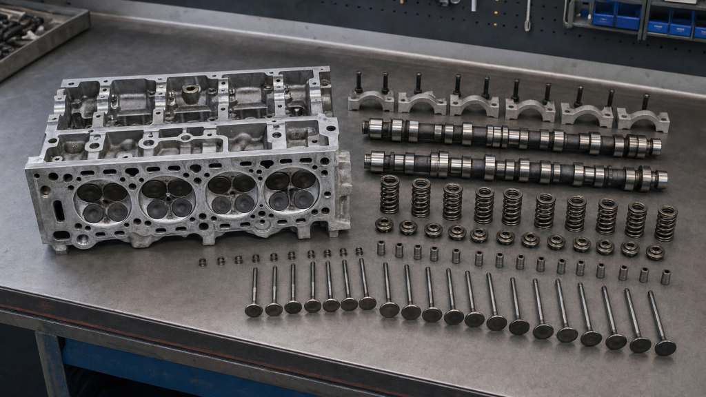
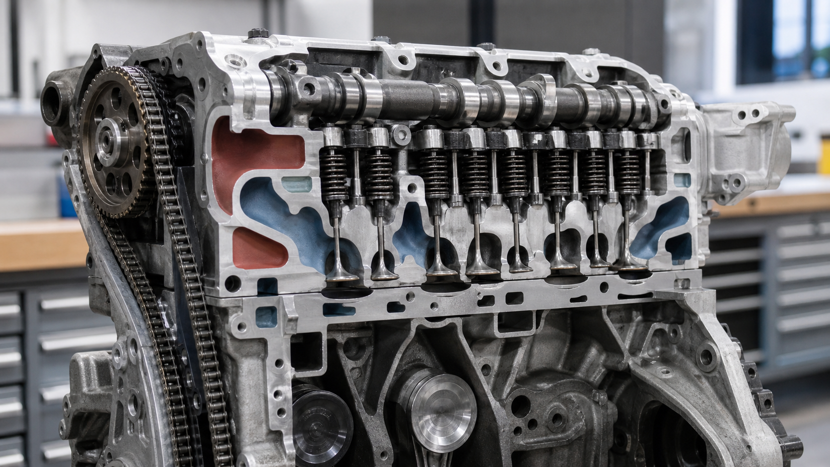
The cylinder head bolts to the engine block’s top surface, forming the upper boundary of each cylinder. Where these two castings meet, a head gasket creates separate seals around combustion chambers, coolant passages, and oil galleries. This clamped joint transforms independent components into a working pressure vessel that contains combustion forces while routing air, fuel, and exhaust through the engine.
A cylinder head performs four integrated functions: it shapes the combustion chamber, routes intake and exhaust flow through machined ports, supports valve operation and timing, and distributes coolant and oil through internal passages. Failure in any area affects the others—a warped deck leaks both compression and coolant, while a cracked casting can mix oil and coolant while dropping cylinder pressure.
Key Takeaways
- The head gasket interface creates separate pressure boundaries for combustion chambers, coolant passages, and oil galleries while clamping the head to the block
- Intake ports feed air or mixture into cylinders; exhaust ports remove combustion gases after the power stroke
- Valve guides, seats, springs, and camshaft bearings mount directly in the head casting
- Internal coolant passages concentrate flow around exhaust ports and combustion chambers; oil passages supply camshaft bearings and valvetrain components
- Head damage creates overlapping symptoms that require measurement with compression testing, leak-down testing, and deck flatness checks rather than visual inspection
The Cylinder Head Is the Engine’s Upper Pressure Boundary
The cylinder head casting closes each cylinder bore at the top. When the piston reaches top dead center during compression, the small volume between the piston crown and the machined chamber surface in the head determines the engine’s compression ratio. Combustion pressure pushes equally against the piston, cylinder walls, and head deck—the flat machined surface where head and block meet.
Head bolts or studs clamp the two castings together. Torque specifications and tightening sequence come from the engine manufacturer because uneven clamping creates leak paths or warps the deck. The head gasket sits between machined surfaces, using layered construction to seal combustion chambers differently than coolant and oil passages.
Cast iron and aluminum heads behave differently under thermal cycling. Iron expands less but adds weight. Aluminum reduces mass but requires different gasket materials and torque specifications because aluminum and iron expand at different rates. Modern multi-layer steel gaskets and composite designs accommodate this movement while maintaining seal integrity across all passages.
How Air, Fuel, Combustion, and Exhaust Pass through the Head
During the intake stroke, the piston moves downward while the intake valve opens. Air or air-fuel mixture enters through the intake port—a curved passage machined from the head’s outer face to the valve seat. Port shape, cross-sectional area, and surface finish affect flow velocity and turbulence, which influence how well the mixture prepares for combustion.
After the intake valve closes, the piston compresses the charge. Ignition occurs near top dead center on the compression stroke. The resulting pressure rise forces combustion gases to expand, driving the piston down on the power stroke. Combustion chamber shape determines how the flame front propagates from the spark plug or injector. A compact chamber with central ignition promotes complete burning, while stretched or offset designs may cause uneven combustion.
The exhaust valve opens before the piston reaches bottom dead center on the power stroke. As the piston rises on the exhaust stroke, it pushes spent gases through the exhaust port toward the manifold. These passages route hot gases away from the combustion chamber, and both port and valve materials must resist thermal fatigue and corrosion.
Valve timing overlap occurs when intake and exhaust valves open simultaneously near top dead center between exhaust and intake strokes. This period helps evacuate remaining exhaust gases and begin filling the cylinder with fresh charge. Overlap duration and valve lift come from camshaft design and cannot be adjusted without changing the cam or using variable valve timing systems where equipped.
Valve and Camshaft Support
The head provides structural mounting for valves, guides, seats, springs, and camshaft bearings. Each valve slides in a guide—either pressed into the casting or formed during casting—that controls stem alignment and limits oil entry into the port. The valve face seals against a hardened seat insert pressed into the head, creating a gas-tight seal under spring pressure.
Valve springs hold valves closed and maintain contact between valvetrain components during operation. Spring tension must overcome valve inertia at high speeds without causing excessive cam wear. Weak or broken springs allow valve float, where the valve doesn’t fully close or follow the cam profile, causing compression loss and potential piston contact.
Overhead cam designs mount the camshaft in the head, either above the valves with a single cam or with separate intake and exhaust cams. Cam lobes act on rocker arms, finger followers, or directly on valve stems. Camshaft journals ride in machined bores or bearing caps, with pressurized oil supplied through drilled passages in the casting.
Valve-train function requires measurement rather than visual inspection. A compression test compares cylinder pressure across all cylinders; significant variation indicates sealing problems. A leak-down test isolates the source by pressurizing each cylinder at top dead center and identifying where air escapes—through intake or exhaust valves, into the cooling system, past the rings, or into the crankcase. Valve lash—the clearance between cam lobe and valve stem when cold—must match the service manual specification; incorrect clearance changes valve timing and causes noise or incomplete sealing.
Cooling and Lubrication inside the Casting
Coolant passages cast or cored into the head surround combustion chambers and exhaust ports. Coolant enters from the engine block through openings in the deck surface, flows through these passages, and exits toward the thermostat housing. Passage design concentrates flow around the hottest areas—near exhaust valves and combustion chambers.
Clogged passages from corrosion or scale redirect flow away from critical zones. Local overheating warps the deck or cracks the casting between valve seats and coolant passages. Flow distribution depends on passage size, casting core placement, and the difference between inlet and outlet pressure.
Oil passages deliver pressurized lubricant to camshaft bearings, rocker arms, and valve stems. On overhead-cam engines, a main gallery feeds oil to the cam towers, where it lubricates bearings and drains back through return passages. Oil spray or splash reaches cam lobes and springs. Restricted supply starves bearings; blocked return passages cause pooling in the valve cover, raising crankcase pressure and forcing oil past seals.
Casting porosity or cracks connecting oil and coolant passages mix the two fluids. Oil in coolant appears as emulsion in the radiator. Coolant in oil shows as light-colored contamination on the dipstick. Pressure testing the cooling system while cold helps locate the leak path before disassembly.
How the Head Seals to the Engine Block
The head gasket creates multiple independent seals: around each combustion chamber, between oil passages, between coolant passages, and between adjacent cylinders. Multi-layer steel gaskets use spring-loaded stainless layers; composite gaskets combine facings with a metal core. Gasket type depends on deck surface finish, material combination, and expected cylinder pressure.
Surface finish directly affects sealing. Decks machined too rough tear gasket facings; surfaces too smooth prevent the soft layer from filling minor irregularities. Service manuals specify finish as a roughness measurement that requires a profilometer to verify. Visual inspection cannot confirm acceptable surface preparation.
Head bolt installation follows a specific torque and angle sequence. Initial torque brings the head into even contact. Subsequent angle steps—typically specified in degrees beyond initial torque—stretch bolts into their elastic range, maintaining clamping force as the gasket compresses and components cycle thermally. Torque-to-yield bolts deform permanently during installation and must be replaced. Reusing these bolts results in insufficient clamp and gasket failure.
Deck flatness determines sealing reliability. Warped decks concentrate clamping force unevenly, leaving gaps at edges or in the center. A straightedge and feeler gauges can detect gross warpage, but precision measurement requires machine-shop equipment. Service manuals specify flatness limits; exceeding these requires resurfacing, though excessive material removal reduces compression height and may require compensating changes.
Repeated gasket failure after correct installation points to an external cause: chronic overheating from cooling-system faults, detonation from incorrect timing or fuel quality, or cylinder pressure beyond design limits from boost or performance modifications. The gasket is responding to conditions it wasn’t designed to withstand.
Common Cylinder Head Designs
Cylinder head architecture varies with engine layout and intended use. The table below compares four configurations:
|
Design |
Camshaft Location |
Valves per Cylinder |
Flow Characteristics |
Common Applications |
|---|---|---|---|---|
|
Overhead Valve (OHV) |
Block-mounted, pushrod-actuated |
2 |
Port shapes constrained by rocker geometry |
Domestic truck V8s, industrial engines |
|
Single Overhead Cam (SOHC) |
Above valves, rocker or follower actuation |
2–3 |
Direct cam actuation improves port design |
Four-cylinder cars, mainstream V6 engines |
|
Dual Overhead Cam (DOHC) |
Separate intake and exhaust cams |
4–5 |
Independent timing control, optimized port angles |
Performance engines, modern turbocharged designs |
|
Crossflow |
Intake and exhaust on opposite sides |
2 |
Straighter ports, improved scavenging |
Some inline and diesel engines |
DOHC designs enable independent intake and exhaust timing adjustment through variable valve timing systems. This capability comes with increased parts count and complexity. OHV designs reduce valvetrain mass and package height but limit high-speed operation due to longer pushrods and greater reciprocating weight.
Combustion chamber shape affects flame propagation and valve sizing. Hemispherical and pent-roof chambers place the ignition source centrally with angled valves, improving burn characteristics and allowing larger valves. Wedge chambers simplify manufacturing with parallel or nearly parallel valve stems while accepting slightly less optimal flow.
Aluminum castings dominate modern passenger vehicles for weight reduction. Cast iron remains common in heavy-duty and commercial applications where durability and lower thermal expansion outweigh mass considerations. Some racing applications use billet-machined heads for maximum port optimization and structural integrity.
What Head Problems Change Engine Behavior
Head damage creates overlapping symptoms because combustion pressure, coolant, oil, and exhaust all pass through the same structure. A crack connecting a combustion chamber to a coolant passage causes compression loss, coolant consumption, white exhaust smoke, and overheating. A crack between cylinders drops compression in both while creating a misfire that moves between adjacent cylinders. Warped decks leak compression and coolant simultaneously, often with visible seepage at the gasket edge.
Diagnostic testing identifies the failure mode. Compression testing shows which cylinders have low pressure but not where pressure escapes. Leak-down testing pressurizes each cylinder at top dead center and reveals the leak path—into the cooling system through a gasket or crack, past rings into the crankcase, through intake or exhaust valves, or between cylinders. A cooling-system pressure test applied cold shows external leaks or combustion-gas intrusion that raises pressure beyond the cap rating.
Valve problems present differently than combustion-chamber damage. A burned valve creates a consistent single-cylinder misfire with low compression during both compression and leak-down testing. Worn valve guides allow oil consumption without compression loss—blue smoke appears on deceleration as manifold vacuum pulls oil down the guide. Broken valve springs cause intermittent misfires at specific engine speeds where spring harmonics allow valve float.
Repair versus replacement decisions depend on what each option includes. Resurfacing the deck and installing a new gasket addresses warpage and sealing but does nothing for cracks, valve damage, or worn guides. A rebuilt head includes new valves, guides, seats, and springs, with crack inspection and deck resurfacing, though core condition affects availability and pricing. A new casting eliminates core-related variables at higher cost.
When requesting quotes, specify the complete scope: diagnostic tests confirming the failure mode, machining operations included, which parts are new versus reused, whether timing components and accessory drive service is included, and warranty terms. Labor estimates must account for engine access—removing intake manifolds, exhaust systems, and wiring often exceeds the time required to remove and install the head itself.
FAQs
Can a cylinder head be repaired if it has a crack?
Repair depends on crack location and length. Cracks in non-structural areas away from combustion chambers, valve seats, and fluid passages can sometimes be pinned or welded by qualified machine shops. Cracks between valve seats, through combustion chambers, or connecting oil and coolant passages typically require replacement because repairs may not survive thermal and pressure cycling. Magnetic particle inspection or dye penetrant testing reveals the full crack extent, including branches invisible to surface inspection.
How do I confirm whether my cylinder head is warped or the gasket simply failed?
Measure deck flatness with a precision straightedge and feeler gauges. Place the straightedge lengthwise, crosswise, and diagonally across the deck. Slide feeler gauges under the straightedge at multiple points. Compare gaps to the service manual’s flatness specification. If the deck exceeds the limit, it requires resurfacing. A flat deck with gasket failure indicates improper installation, incorrect torque, or an underlying condition like chronic overheating that must be corrected.
What is the difference between a cylinder head and a valve cover?
The valve cover is a shallow housing that bolts to the top of the cylinder head, sealing the valvetrain and containing oil splash. It carries no combustion pressure or coolant and can be removed for valve adjustments without major disassembly. The cylinder head forms the combustion chamber, houses valves and ports, and bolts to the engine block under high clamping force. Valve cover work is routine maintenance; head removal is major repair.
Do all cylinder heads use the same number of valves per cylinder?
No. Two valves per cylinder—one intake, one exhaust—is the minimum configuration and remains common in cost-sensitive and heavy-duty applications. Three-valve designs add a second intake valve for improved airflow. Four-valve layouts use two intake and two exhaust valves, increasing total valve area and enabling better port shapes. Five-valve designs appeared in some performance engines but added complexity without proportional benefit. Valve count affects parts cost, machining requirements, and repair time.
Can cylinder head bolts be reused after head removal?
Only if they are not torque-to-yield design. Torque-to-yield bolts stretch permanently during installation and lose clamping force if reused, leading to gasket failure. The service manual or parts supplier identifies bolt type. Standard bolts can be reused if threads are undamaged and they show no necking or corrosion. When uncertain, replace bolts—their cost is minimal compared to repeating the job after gasket failure from insufficient clamping force.
Conclusion
The cylinder head seals the top of each cylinder while routing airflow, timing combustion, and managing heat through integrated port, valve, cooling, and lubrication systems. Diagnosing head problems requires measurement: compression and leak-down testing isolate where pressure escapes, deck flatness measurements determine resurfacing needs, and cooling-system pressure tests confirm whether cracks or gasket failure connect combustion and coolant spaces. When evaluating repair or replacement, request quotes specifying diagnostic methods used, machining operations included, parts scope, timing component service, and warranty terms. Complete documentation prevents scope expansion and ensures the work matches your engine’s design requirements and material specifications. Reference your engine’s service manual for torque specifications, flatness limits, and surface-finish requirements specific to your engine family.