The camshaft and crankshaft meet at the timing drive, where a 2:1 ratio keeps valve events synchronized with piston position through every four-stroke cycle. The crankshaft converts combustion pressure into rotating torque at engine speed. The camshaft opens and closes valves at half that speed. Understanding which shaft controls which event, how the timing drive maintains their phase relationship, and which symptoms point to each system separates valve-timing faults from bearing failures before disassembly.
This comparison organizes the mechanical relationship around the four-stroke timing requirement, showing how valve scheduling and torque production depend on two shafts with different speeds, loads, and failure modes.
Key Takeaways
- The crankshaft rotates at engine speed and converts reciprocating piston motion into rotational torque; the camshaft rotates at half engine speed and actuates valves through lobes.
- Timing chains, belts, or gears maintain a 2:1 speed ratio so the camshaft completes one rotation for every two crankshaft rotations, matching valve events to piston position.
- Crankshaft position sensors trigger ignition and fuel injection; camshaft position sensors identify which cylinder is on compression stroke and enable sequential injection.
- Crankshaft main bearings carry combustion loads and inertia forces; camshaft bearings carry valve spring loads and timing-drive tension.
- Failure symptoms separate by function: misfires, rough idle, and timing codes point to camshaft or timing-drive issues; knock, vibration, and oil-pressure loss point to crankshaft or main bearing faults.
One Engine Cycle, Two Different Shafts
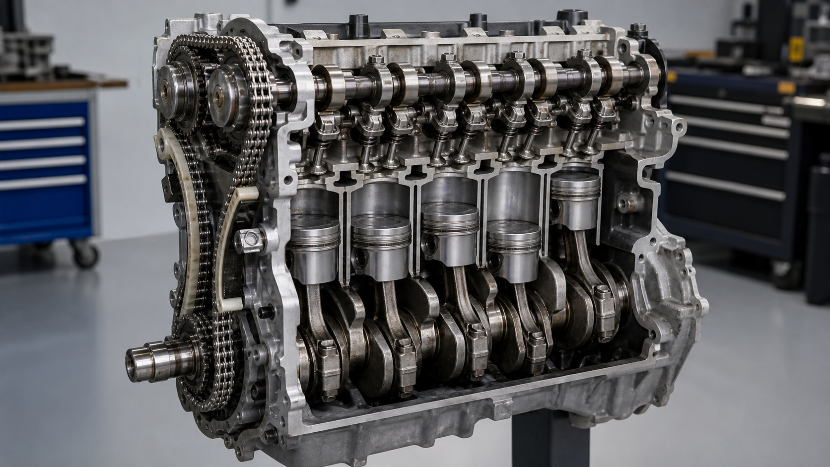
A four-stroke engine completes one power cycle across 720 crankshaft degrees: intake, compression, power, and exhaust. The crankshaft turns twice during that cycle. Each valve must open and close once per cycle, requiring the camshaft to rotate only once during the same 720 degrees. The timing drive—chain, belt, or gear set—connects the two shafts and enforces the 2:1 speed ratio.
The crankshaft sits in the engine block, supported by main bearings that carry combustion forces and rotating mass. It drives the transmission, oil pump, and the timing component that turns the camshaft. The camshaft sits either in the cylinder head or in the block. Its lobes push against lifters, rockers, or direct-acting followers to open valves against spring pressure. Both shafts turn continuously while the engine runs but handle different mechanical tasks under different load conditions.
What the Crankshaft Does with Combustion Force
The crankshaft has offset journals called rod journals where connecting rods attach. When combustion pressure pushes a piston down during the power stroke, the connecting rod transfers that linear force to the rod journal. The offset between the rod journal centerline and the main journal centerline creates a lever arm that converts the push into rotational torque. The crankshaft collects torque pulses from all cylinders and delivers rotating power to the flywheel and transmission.
Crankshaft design handles bending, torsional twist, and inertia loads. The main journals sit in the block’s main bearing saddles. Counterweights offset the rotating and reciprocating mass, reducing vibration and main bearing loads. Forged steel crankshafts provide higher strength; cast-iron crankshafts serve lower-stress applications.
Crankshaft position sensors—magnetic or Hall-effect types—read a toothed reluctor wheel or timing marks on the crank pulley or flywheel. The engine control module uses this signal to calculate engine speed, piston position, and ignition timing. The crankshaft completes two full rotations per combustion cycle, so the position sensor alone cannot identify which cylinder is on compression stroke. That requires the camshaft position sensor.
What the Camshaft Does with Valve Timing
The camshaft has eccentric lobes machined along its length, one or more for each valve. As the camshaft rotates, each lobe pushes a lifter, rocker arm, or follower to open the valve. The lobe profile controls valve lift, duration, and opening rate. Spring pressure closes the valve when the lobe base circle rotates back under the lifter. Valve timing determines when intake and exhaust events occur relative to piston position, directly affecting volumetric efficiency and power delivery.
The camshaft rotates at half engine speed because each valve opens once per four-stroke cycle, and the cycle spans two crankshaft revolutions. An intake valve opens near top dead center on the intake stroke, stays open while the piston descends, and closes after bottom dead center. The exhaust valve opens before bottom dead center on the power stroke and closes after top dead center on the exhaust stroke. If the camshaft ran at engine speed, valves would open twice per cycle, breaking the four-stroke sequence.
Overhead-cam engines mount the camshaft directly above the valves in the cylinder head, reducing valvetrain mass and allowing higher engine speeds. Pushrod engines place the camshaft in the block and use pushrods to actuate rocker arms in the head. The camshaft is driven by the crankshaft through a timing chain, belt, or gear set. The timing component must maintain accurate phase alignment; if the camshaft advances or retards relative to the crankshaft, valve timing shifts and performance suffers.
Variable valve timing systems adjust camshaft phase while the engine runs, using oil pressure to rotate a phaser mechanism. The camshaft position sensor reads slots or teeth on the camshaft sprocket or a reluctor on the camshaft. The signal tells the control module which cylinder is ready for injection and spark, enabling sequential fuel injection and ignition control across all cylinders.
Speed, Location, Bearings, and Load Differences
The crankshaft and camshaft differ in rotation speed, installed position, bearing design, and mechanical loading. These differences determine material selection, machining tolerances, and failure modes.
Rotation Speed
The crankshaft rotates at engine speed. At 3,000 engine rpm, the crankshaft completes 3,000 revolutions per minute. The camshaft rotates at half that speed—1,500 rpm at the same engine speed—because of the 2:1 timing-drive ratio. Lower rotational speed reduces inertia loads on camshaft bearings but does not eliminate wear, because the lobes generate side loads each time they actuate a valve.
Location
The crankshaft sits in the lower engine block, supported by main bearing caps or a ladder frame bolted to the block deck. The crankshaft centerline is below the cylinder bores, and the shaft runs the length of the engine. Camshaft location depends on engine architecture. In overhead-cam designs, one or two camshafts sit in the cylinder head, directly above the valves. In pushrod engines, the camshaft sits in the block, above the crankshaft, and drives valves through lifters, pushrods, and rocker arms.
Bearings
Crankshaft main bearings are plain journal bearings, consisting of split-shell inserts with a steel back and a soft bearing material such as aluminum-tin or copper-lead alloy. The bearings fit into the main bearing saddles in the block and are clamped by bearing caps. Oil pressure feeds the bearings through drilled passages in the block and crankshaft. Crankshaft bearings handle high combustion loads, inertia forces, and continuous rotation.
Camshaft bearings are also plain journal bearings but experience lower loads because valve springs and friction are the primary forces. In overhead-cam engines, the camshaft often runs in bearing caps bolted to the cylinder head, with oil passages in the head supplying lubrication. In block-mounted camshafts, the bearings are pressed into bores machined directly into the block. Camshaft bearing clearances and oil supply affect valvetrain noise and timing accuracy.
Load Conditions
The crankshaft handles peak combustion pressure transferred through the connecting rod, plus inertia loads from the rotating assembly. The camshaft handles valve spring pressure, which varies by engine design, multiplied by the number of valves being actuated at any moment. Timing-drive tension also loads the camshaft. Crankshaft failures typically result from bearing failure, fatigue cracks, or torsional resonance. Camshaft failures result from lobe wear, bearing seizure, or timing-drive tooth damage.
How the Timing Drive Keeps Them in Phase
The timing drive maintains the 2:1 speed ratio and phase relationship between the crankshaft and camshaft. Three drive types are common: timing chains, timing belts, and gear sets. Each has different service intervals, failure modes, and inspection requirements.
Timing Chains
A timing chain wraps around a sprocket on the crankshaft and a larger sprocket on the camshaft. The camshaft sprocket has twice the number of teeth as the crankshaft sprocket, creating the 2:1 ratio. Chains run inside the engine, lubricated by engine oil. Chain tensioners—spring-loaded or hydraulic—maintain proper tension as the chain stretches. Chain guides, often plastic-backed, prevent the chain from whipping or contacting the cover. Chain wear shows as slack, rattling noise at idle, and eventual timing drift that retards the camshaft. Worn chains can jump teeth, instantly changing valve timing and causing piston-to-valve contact in interference engines.
Timing Belts
A timing belt uses toothed rubber construction and runs on toothed sprockets. Belts operate dry, outside the engine, under a protective cover. Belt tension is critical; too loose and the belt can skip teeth, too tight and bearing loads increase. Belts have a defined service life specified by the manufacturer and must be replaced on schedule because they do not give warning before failure. A broken timing belt stops the camshaft while the crankshaft continues to rotate, causing immediate valve-to-piston contact in interference engines. Belt inspection includes checking for cracking, glazing, tooth damage, and oil contamination, which weakens the rubber.
Gear Sets
Some engines use direct gear drive between the crankshaft and camshaft, common in older pushrod engines and certain racing applications. The crankshaft gear meshes directly with the camshaft gear, and the camshaft gear has twice the diameter or number of teeth. Gear drives are durable and require no maintenance but are noisier than chains or belts and are limited to engines where the camshaft is close to the crankshaft. Timing gears are made from steel or sintered metal and run splash-lubricated or without lubrication depending on design.
Phase alignment is set during initial assembly using timing marks stamped or cast onto the sprockets or gears. If the timing drive is removed or replaced, the marks must be realigned or the engine will not run. Even a one-tooth error causes rough idle, reduced power, and diagnostic codes. Timing-component inspection during a teardown includes measuring chain stretch, checking sprocket wear, verifying tensioner function, and confirming guide condition.
Symptoms and Tests That Separate Camshaft from Crankshaft Faults
Diagnosing whether a problem originates in the crankshaft system or the camshaft system requires understanding which symptoms map to which mechanical function. Sensor codes, noise character, test results, and operating conditions narrow the diagnosis before disassembly.
Sensor Codes and Fuel-Injection Issues
A crankshaft position sensor fault typically triggers a no-start condition or intermittent stalling because the control module cannot calculate engine speed or piston position without the signal. The engine may crank but not fire, or it may start and die immediately. A camshaft position sensor fault allows the engine to run but may prevent sequential fuel injection, forcing the system into batch-fire mode. The result is often rough idle, slight power loss, and a check-engine light with a cam sensor code. If both sensors fail, the engine will not start.
Correlation codes appear when the control module detects a timing mismatch between the crankshaft and camshaft signals. This indicates the timing chain or belt has stretched, jumped, or broken partially. The engine may still run but will have rough idle, reduced power, and poor fuel economy. A stretched chain that retards cam timing closes the intake valve early, reducing cylinder fill and lowering power.
Noise and Vibration
Crankshaft-related noise is a deep knock or rumble, synchronized with engine speed. A worn main bearing produces a heavy knock that worsens under load. A spun bearing creates immediate loud knocking and oil-pressure loss. Crankshaft imbalance or a broken counterweight causes vibration that increases with rpm.
Camshaft noise is a ticking or tapping sound, faster than crankshaft knock and often most audible at idle. Worn cam lobes or collapsed lifters produce valvetrain clatter. Timing-chain rattle occurs on startup when oil pressure is low and the tensioner has not yet extended. The noise disappears once the tensioner pressurizes. A failed chain tensioner or guide creates a slapping sound that varies with rpm.
Oil Pressure and Bearing Condition
Low oil pressure at idle, especially when the engine is warm, points to worn crankshaft main bearings or rod bearings. Bearing clearance increases as the soft bearing material wears, allowing more oil to escape and reducing pressure. A crankshaft with excessive runout or journal damage accelerates bearing wear. Oil-pressure tests at idle and at higher rpm, compared against service manual specifications, confirm whether main bearing clearance is excessive.
Camshaft bearing wear rarely causes low oil pressure because camshaft loads are lower and oil flow through cam bearings is smaller. However, a seized camshaft bearing can cause localized overheating and lobe damage.
Compression and Leak-Down Tests
Compression and leak-down tests help separate valve-timing problems from worn piston rings or valve sealing issues. If compression is low across all cylinders and a leak-down test shows air escaping through the intake or exhaust, the problem may be valve-related. If timing has jumped, valves may open or close at the wrong point in the cycle, reducing effective compression. A compression test alone cannot distinguish between jumped timing and mechanical wear, so a leak-down test and timing verification are both needed.
Timing Verification
Confirming cam timing requires removing the timing cover and checking the alignment marks on the sprockets or gears. Some engines have windows in the timing cover or access plugs that allow mark inspection without full disassembly. If the marks are off by one or more teeth, the timing drive has jumped or was installed incorrectly. Variable valve timing systems require a scan tool to check actual cam advance or retard compared to commanded position. Stuck phasers or blocked oil passages prevent the system from adjusting timing, triggering performance codes and reducing power.
Camshaft vs Crankshaft Comparison Table
|
Feature |
Crankshaft |
Camshaft |
|---|---|---|
|
Function |
Converts reciprocating piston motion into rotational torque |
Opens and closes valves at timed intervals through lobes |
|
Rotation Speed |
Engine speed (3,000 rpm at 3,000 engine rpm) |
Half engine speed (1,500 rpm at 3,000 engine rpm) |
|
Drive Ratio |
1:1 with flywheel and transmission input |
2:1 with crankshaft through timing chain, belt, or gears |
|
Location |
Lower engine block, supported by main bearings |
Cylinder head (overhead cam) or engine block (pushrod) |
|
Primary Load |
Combustion pressure, inertia forces, rotating mass |
Valve spring pressure, timing drive tension, friction |
|
Bearing Type |
Plain journal bearings, high-load capacity, pressure-fed oil |
Plain journal bearings, lower load, splash or pressure-fed oil |
|
Position Sensor Function |
Provides engine speed and piston position for ignition and fuel timing |
Identifies cylinder position for sequential fuel injection |
|
Failure Symptoms |
Knock, vibration, oil-pressure loss, deep rumble, bearing debris in oil |
Valve clatter, rough idle, misfires, timing codes, chain rattle |
|
Common Failure Modes |
Bearing wear, journal scoring, cracks, spun bearings, imbalance |
Lobe wear, bearing seizure, timing-chain jump, phaser failure |
|
Inspection Access |
Requires oil pan removal or complete teardown |
Timing cover removal for chain inspection; head removal for cam inspection |
FAQs
Can the engine run if the camshaft position sensor fails but the crankshaft sensor works?
Yes, most engines can run with a failed camshaft position sensor because the crankshaft sensor provides engine speed and piston position for ignition timing. The control module may switch to batch fuel injection instead of sequential injection, and a check-engine light will appear. Performance may be slightly reduced, but the engine will start and drive.
Why does the camshaft rotate at half the crankshaft speed in a four-stroke engine?
Each valve must open and close once per combustion cycle, which spans 720 crankshaft degrees or two crankshaft revolutions. If the camshaft rotated at engine speed, valves would open twice per cycle, disrupting the intake-compression-power-exhaust sequence. The 2:1 ratio ensures one camshaft rotation per cycle, matching valve events to piston position.
How do you confirm whether a timing chain has jumped or stretched?
Remove the timing cover and check the alignment marks on the crankshaft and camshaft sprockets. If the marks are off by one or more teeth from the factory specification, the chain has jumped. A stretched chain that has not jumped may still show marks aligned but will have excessive slack between the sprockets. A scan tool can compare commanded cam timing to actual timing in variable valve timing systems.
Does a worn camshaft lobe cause low compression in that cylinder?
A worn camshaft lobe reduces valve lift and duration, which can lower volumetric efficiency and reduce compression slightly, especially if the intake valve does not open fully. However, low compression is more often caused by worn piston rings, a blown head gasket, or a burned valve. A leak-down test helps separate valvetrain issues from sealing problems in the combustion chamber.
What happens if the crankshaft and camshaft timing marks are one tooth off during installation?
The engine may start but will run poorly. Valve timing will be advanced or retarded depending on the direction of the error, causing rough idle, reduced power, and potentially triggering codes. In interference engines, being off by multiple teeth can cause pistons to contact valves, bending valves and damaging pistons. Always verify timing marks during installation and rotate the engine by hand two full revolutions before starting.
Conclusion
The camshaft and crankshaft perform separate jobs within a synchronized system: the crankshaft converts combustion force into rotational power, and the camshaft controls valve events at half engine speed. Diagnosing faults between the two systems depends on understanding which symptoms—knock versus clatter, sensor codes versus compression loss, oil pressure versus timing drift—point to each shaft. If you hear noise, see timing codes, or measure compression loss, verify sensor signals, timing-mark alignment, and bearing clearances with measurements and service manual specifications before ordering parts. When sourcing replacement camshafts, crankshafts, or timing components, confirm fitment with the engine family, casting number, and any variable valve timing hardware included in the assembly.