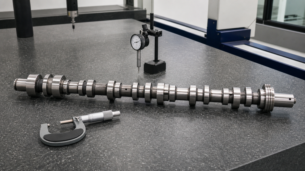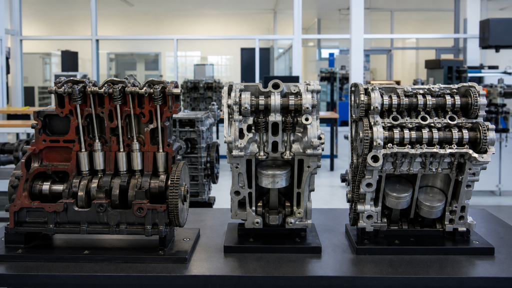
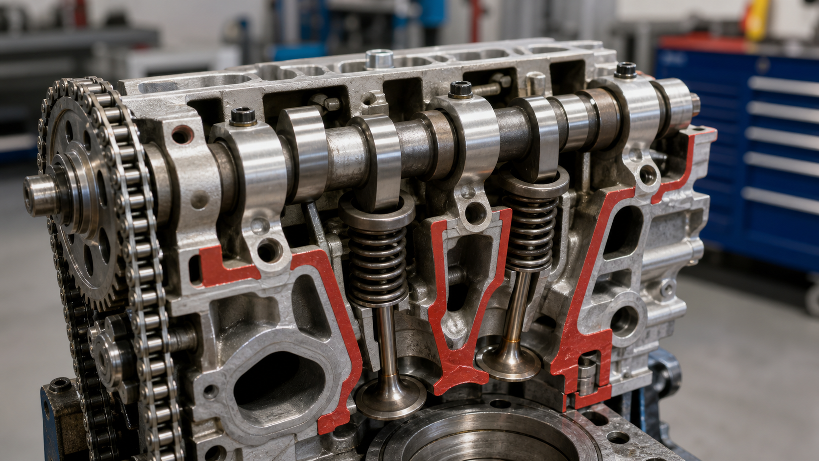
When an intake valve opens, drops into the cylinder, holds for a portion of crankshaft rotation, then closes, a camshaft lobe has completed one valve event. That rotating shaft, machined with eccentric lobes and journals, translates rotation into timed vertical motion that fills cylinders, exhausts combustion gases, and controls engine breathing. Every valve opening and closing in a four-stroke engine results from a cam lobe pushing a follower, lifter, or rocker arm that moves the valve stem. Understanding what a camshaft is means following one lobe through its rotation and watching how its changing radius creates lift, duration, and timing.
Key Takeaways
- A camshaft converts rotary motion into timed valve lift through eccentric lobes machined onto a rotating shaft.
- Lobe profile—base circle, ramp, flank, nose—determines valve lift, duration, and the rate of opening and closing.
- Camshaft position (overhead or in-block) defines valvetrain architecture: OHV uses pushrods, SOHC and DOHC place cams above the valves.
- Timing chains, belts, or gears synchronize camshaft rotation to crankshaft rotation, maintaining correct valve-to-piston relationship.
- Wear in cam lobes, followers, bearings, or drive components changes valve timing, lift, and sealing, producing measurable performance loss.
The Short Answer: A Camshaft Schedules Every Valve Event
A camshaft is a machined steel shaft fitted with eccentric lobes, each positioned to open one valve at a specific crankshaft angle. The shaft rotates at half crankshaft speed in four-stroke engines, so each lobe completes one lift cycle per combustion cycle. One lobe serves each valve; a four-cylinder engine with two valves per cylinder uses a camshaft with eight lobes. The lobe profile—the changing radius from base circle to peak—defines how far the valve opens (lift), how long it stays open (duration), and how quickly it accelerates and decelerates (ramp rate). The camshaft does not push the valve directly in most designs; instead, the lobe contacts a follower, lifter, or rocker arm that transmits motion to the valve stem.
The camshaft’s job is to open each valve at the correct crankshaft angle, hold it open for the required duration, and close it before the piston arrives. Intake valves open before top dead center on the intake stroke, stay open past bottom dead center, and close after the piston begins compression. Exhaust valves open before bottom dead center on the power stroke and close after top dead center on the intake stroke. This overlap—when both intake and exhaust valves are open—improves cylinder scavenging at higher engine speeds. The camshaft’s lobe centerlines, measured in degrees, control these events. Changing the camshaft or advancing its timing shifts every valve event, altering engine breathing, torque curve, and emissions.
From Cam Lobe Rotation to Valve Motion
A cam lobe is not a simple eccentric circle; it is a precision-ground profile with four functional zones. The base circle is the smallest radius, where the lobe does not lift the follower and the valve remains closed under spring pressure. As the camshaft rotates, the lobe enters the opening ramp, a gradual radius increase that takes up lash and begins lifting the valve without shock. The flank is the steepest section, where the radius increases rapidly and the valve accelerates to maximum lift. At the nose, the lobe reaches its largest radius and the valve hits peak lift, holding briefly before the closing flank and ramp bring it back to the base circle. The difference between base circle radius and nose radius, multiplied by the rocker ratio if a rocker arm is used, determines total valve lift.
When the camshaft rotates, the lobe’s changing radius pushes a follower, bucket tappet, roller lifter, or rocker arm. The follower rides on the lobe surface and transmits vertical motion. In pushrod engines, the lifter sits in the block, rides the cam lobe, and pushes a pushrod up to a rocker arm, which pivots and opens the valve. In overhead-cam engines, the lobe acts directly on a bucket tappet or through a rocker arm. The lobe profile must accelerate the valve smoothly to avoid valvetrain bounce, maintain contact at high RPM, and decelerate before the valve slams onto its seat. This profile is calculated to balance lift, duration, and acceleration for a given spring rate, mass, and engine speed range.
Duration is measured in crankshaft degrees, not time. A lobe with typical intake duration might open the valve shortly before top dead center and close it well past bottom dead center, with the exact timing varying by design. At 3,000 RPM, a given duration equals more time than the same angular duration at 6,000 RPM. The camshaft does not adjust for engine speed; it delivers the same angular duration regardless of RPM. This fixed relationship means a camshaft optimized for low-speed torque will have short duration and low lift, while a high-RPM camshaft will have long duration and high lift, trading low-speed cylinder filling for high-speed breathing.
Lift, Duration, Lobe Separation, and Timing
Valve lift, duration, lobe separation angle, and installed timing are the four variables that define camshaft behavior. Lift is the maximum distance the valve moves off its seat, measured in millimeters or inches. More lift allows more air and fuel into the cylinder, but it also increases valvetrain stress, requires stiffer springs, and can cause piston-to-valve contact if clearance is insufficient. Lift is limited by valve-to-piston clearance, retainer-to-seal clearance, and the spring’s ability to control the valve at high RPM.
Duration is the number of crankshaft degrees the valve stays open, commonly measured at a specified lift point to eliminate lash variation. Longer duration keeps the valve open past the piston’s geometric stroke limits, improving cylinder filling at high RPM but reducing low-speed torque because the valve is still open when the piston begins its compression stroke. Short-duration camshafts close the valve earlier, trapping more mixture and building more cylinder pressure at low engine speeds.
Lobe separation angle (LSA) is the angle in camshaft degrees between the intake lobe centerline and the exhaust lobe centerline. A wide LSA reduces overlap, producing smooth idle, better low-speed torque, and lower emissions. A narrow LSA increases overlap, improving high-RPM breathing and scavenging but causing rough idle and lower vacuum. Lobe separation is ground into the camshaft and cannot be changed without replacing the cam.
Installed timing is the relationship between the camshaft’s centerline and the crankshaft’s position. Advancing the camshaft (installing it ahead of its original position) moves all valve events earlier, improving low-RPM torque but reducing peak power. Retarding the camshaft delays all valve events, improving top-end power but sacrificing low-speed response. Installed timing is adjusted with offset cam keys, vernier gears, or adjustable cam sprockets. Proper timing verification requires degree wheel measurement, not just aligning timing marks.
Where Camshafts Sit in OHV, SOHC, and DOHC Engines
Camshaft placement defines valvetrain architecture and affects engine packaging, weight, and RPM capability. Overhead valve (OHV) engines mount the camshaft in the engine block, riding in journals machined into the block casting or in a separate camshaft carrier. The camshaft drives lifters that push pushrods up through the block to rocker arms on the cylinder head. The rocker arms pivot and open the valves. This design is compact, allows a short engine height, and places the heavy camshaft low in the engine for a lower center of gravity. The long valvetrain path—cam lobe to lifter to pushrod to rocker—limits RPM capability because of inertia and flex, but OHV engines are common in trucks and V8 applications where low-speed torque and packaging matter more than high-RPM power.
Single overhead cam (SOHC) engines place one camshaft in the cylinder head, above the valves. The camshaft may act directly on bucket tappets (direct-acting) or through rocker arms (finger followers). Direct-acting designs reduce valvetrain mass and allow higher RPM but require shim-under-bucket valve adjustment. Rocker designs allow simpler adjustment and can multiply cam lift through rocker ratio. SOHC engines with two valves per cylinder use one camshaft to operate both intake and exhaust valves. Four-valve SOHC engines require long rocker arms to reach both intake and exhaust valves from a single cam centerline, adding complexity and reducing efficiency at high RPM.
Dual overhead cam (DOHC) engines use two camshafts per cylinder head: one for intake valves, one for exhaust valves. Each camshaft typically acts directly on the valves through bucket tappets or short rocker arms. This design allows independent control of intake and exhaust timing, reduces valvetrain mass, permits four or five valves per cylinder, and supports higher RPM. DOHC engines are common in performance applications and modern multi-valve designs. The tradeoff is added complexity, higher parts count, and more demanding timing chain or belt routing because both camshafts must be driven from the crankshaft.
How the Camshaft Stays Synchronized with the Crankshaft
The camshaft must rotate at exactly half crankshaft speed to open and close valves at the correct piston positions. This 2:1 ratio is maintained by a timing chain, timing belt, or gear train connecting the crankshaft sprocket or gear to the camshaft sprocket or gear. The crankshaft sprocket has half the tooth count of the camshaft sprocket, so every two crankshaft revolutions produce one camshaft revolution. If the timing drive slips, stretches, or breaks, valve timing shifts relative to piston position, and the engine loses compression, runs poorly, or suffers valve-to-piston contact that bends valves or damages pistons.
Timing chains are steel roller chains running on sprockets, typically lubricated by engine oil. Chains are durable and require no scheduled replacement in most applications, but they stretch over time as pins and rollers wear. A stretched chain retards camshaft timing, delaying valve events and reducing engine performance. Chain tensioners and guides compensate for stretch until wear exceeds their adjustment range. Excessive chain stretch produces rattling noise on startup, poor idle, reduced power, and increased emissions. Chain replacement requires removing the front cover, aligning timing marks, and verifying camshaft centerline position with a degree wheel.
Timing belts are reinforced rubber belts with molded teeth, running on toothed pulleys. Belts are quieter than chains and require no lubrication, but they have a service life—typically specified by the manufacturer based on mileage or time—and must be replaced before they fail. A broken timing belt allows the camshaft to stop while the crankshaft continues rotating. In interference engines, where valve-open positions overlap piston top dead center positions, this results in valves striking pistons, bending valves, and damaging piston crowns. Timing belt replacement is scheduled maintenance, not a repair triggered by symptoms. The replacement interval comes from the service manual, not from belt appearance.
Gear drives use meshing steel gears between crankshaft and camshaft, common in older designs, diesel engines, and some performance applications. Gears are the most durable timing drive, produce no stretch, and require no tensioner, but they are noisy and add weight. Gear-driven camshafts sit close to the crankshaft centerline, limiting overhead-cam placement to dual-cam designs where an intermediate gear or short chain reaches the cylinder head.
What Changes When a Camshaft or Its Drive Wears
Camshaft wear begins at the lobe surface, where the follower rides under high contact stress and reciprocating load. Lobe wear flattens the nose, reduces valve lift, and rounds the opening and closing ramps. Worn lobes reduce valve lift, decreasing airflow and cylinder filling. The valve may no longer reach full lift, and the effective duration shortens because the valve spends less time at usable lift. Worn lobes produce low compression, poor idle, reduced power, and increased emissions. In severe cases, a flat lobe prevents the valve from opening, causing a dead cylinder.
Follower or lifter wear compounds lobe damage. A worn flat tappet develops a concave face, concentrating load on the lobe edges and accelerating wear. Roller lifters resist wear better but can fail if the roller bearing seizes, causing the roller to skid across the lobe and score the surface. Hydraulic lifters wear internally, losing their ability to take up lash, and produce valvetrain noise even when the lobe is intact. Rocker arm wear occurs at the valve tip contact point or the pivot, increasing lash and reducing effective lift.
Camshaft journal and bearing wear changes camshaft position and alignment. Excessive journal wear allows the camshaft to move axially or radially, shifting lobe centerlines and altering valve timing. Bearing clearance beyond specification reduces oil pressure, starving downstream components. Thrust bearing wear permits camshaft end play, allowing the cam to move fore and aft, which can cause timing gear or sprocket misalignment and accelerate timing chain or belt wear.
Timing drive wear—stretched chain, worn belt, or damaged gear—retards camshaft timing even if the cam lobes and followers are intact. A stretched chain retards the camshaft, delaying intake valve opening and closing, reducing overlap, and shifting the torque curve lower in the RPM range. The engine loses top-end power, idles roughly, and may fail emissions testing. Belt wear shows as cracked or frayed teeth, missing chunks, or oil contamination (if a front seal leaks onto the belt). Gear wear produces noise, backlash, and timing drift.
Diagnosing camshaft or timing drive condition requires measurement, not appearance. Valve lift is measured with a dial indicator on the valve retainer while rotating the engine. Compare measured lift to service manual specification. Duration and timing are verified with a degree wheel bolted to the crankshaft and a dial indicator on the valve. Lobe centerline position is checked against the manufacturer’s specification or a known-good baseline. Bearing clearance is measured with Plastigage or a micrometer on the journals and inside diameter bore. Timing chain stretch is assessed by measuring the span between pins over a specified number of links, or by measuring tensioner position. Belt condition is assessed visually and by replacement interval, not by appearance alone. When measurements exceed specification, replacement is required; surface condition is secondary evidence.
FAQs
Can I replace just the camshaft without replacing lifters or followers?
Replacing only the camshaft while reusing worn lifters or followers transfers the old wear pattern to the new cam lobes, causing rapid wear and early failure. Lifters and cam lobes wear in as a matched set, developing complementary surface patterns. A new camshaft requires new lifters or followers, proper break-in lubrication, and controlled engine speed during the first operating cycle. Reusing lifters on a new cam is acceptable only if the lifters show no wear, the original cam had minimal wear, and the same lifter returns to its original lobe position. Roller lifters are more tolerant of reuse than flat tappets, but inspection for roller bearing condition and body wear is still required.
How does variable valve timing affect camshaft function?
Variable valve timing (VVT) systems rotate the camshaft sprocket or pulley relative to the camshaft, advancing or retarding all valve events without changing lobe profile. The engine control module commands a phaser (cam sprocket with internal vanes) or adjustable cam gear to shift camshaft position based on engine speed, load, and temperature. This allows the engine to optimize valve timing for low-speed torque, high-speed power, fuel economy, and emissions across the operating range. The camshaft itself remains unchanged; only its installed timing position shifts. VVT systems add solenoid valves, oil control passages, phasers, and position sensors, all of which require diagnosis when valve timing falls outside specification.
What causes the camshaft position sensor to fail?
The camshaft position sensor reads a reluctor wheel, tone ring, or machined feature on the camshaft to tell the engine control module the camshaft’s rotational position. Sensor failure is caused by heat, vibration, oil contamination, or internal winding breakdown. A failed sensor produces a loss of sync signal, preventing the ECM from calculating ignition timing and fuel injection timing, and the engine may not start or may run poorly. Intermittent sensor failure causes random misfires, stalling, or rough idle. The sensor itself is usually replaced rather than repaired. Diagnosing sensor failure requires an oscilloscope or scan tool to verify signal presence and pattern, not just checking for a stored code.
Do overhead cam engines require different oil than pushrod engines?
Both overhead cam and pushrod engines require engine oil meeting the viscosity and specification listed in the service manual. The difference is that overhead cam engines typically require lower-viscosity oil to ensure oil reaches the camshaft bearings and valve lash adjusters quickly on cold starts, while pushrod engines may specify higher-viscosity oil. The oil specification (API, ILSAC, ACEA) matters more than viscosity because it controls anti-wear additives, detergents, and friction modifiers. Using the wrong specification—particularly low-ZDDP oil in a flat-tappet camshaft engine—causes accelerated cam and lifter wear.
How do I know if my engine has an interference or non-interference design?
An interference engine has valve-open positions that overlap piston top dead center positions, meaning a broken timing belt or jumped timing chain will cause valves to strike pistons. A non-interference engine has sufficient clearance between valves and pistons at all positions, so timing failure causes the engine to stop running but does not cause internal damage. The engine’s interference status is listed in the service manual, timing belt replacement procedures, or technical service bulletins. Many modern engines are interference designs because tighter valve-to-piston clearance allows higher compression ratios and better fuel economy. Determining interference status by measurement requires removing the cylinder head, installing the camshaft in its most advanced and retarded positions, rotating the crankshaft, and measuring piston-to-valve clearance with clay or a dial indicator.
Conclusion
A camshaft translates crankshaft rotation into timed vertical valve motion through machined lobe profiles, synchronized drive systems, and valvetrain components that amplify or transmit lift to the valve stem. Understanding what a camshaft does—and how lift, duration, lobe separation, and timing change engine behavior—begins with following one lobe from base circle to peak lift and back. When diagnosing performance loss, rough idle, low compression, or timing-related codes, start with measured valve lift, lobe centerline verification, and timing chain or belt condition checks rather than visual inspection alone. Before replacing a camshaft, confirm whether the root cause is lobe wear, follower damage, bearing clearance, or timing drive stretch, and document whether the replacement scope includes lifters, timing components, and related valvetrain parts that wear as a matched set. If sourcing camshafts or related components, request material specifications, lobe profile data, and confirmation that bearings, thrust plates, and drive components match the engine family and service manual requirements rather than accepting generic interchange claims.
Related Resources: